
Copyright © 2010-2011,
Thomas Schmid,
Matt Smith,
Ye-Sheng Kuo,
Lohit Yerva,
and Prabal Dutta.
Timers are some of the most fundamental peripherals found in embedded microcontrollers. They are used in many application scenarios, like driving motors, measuring frequencies, or measuring the event time of a particular interrupt.
The purpose of this lab is to learn about the importance of timers and clocks in embedded systems.
You have encountered the clock system of the SmartFusion before. The bus
system AHBlite or APB3 both use the FAB_CLOCK configured in the MSS
Configurator's Clock Management block. The Clock Management has the
possibility to configure several different clocks. One of them is the clock
going into the MSS (free running clock FCLK) and clocking most of
the MSS Peripherals (exception is the 10/100 Ethernet which has its own
clock). The other clocks can be fed into the FPGA. While the MSS clock FCLK
has a recommended maximum of 100 MHz, the FPGA can use faster clocks,
depending on the logic.
In this lab, we will run the FAB_CLK at 40 MHz. To do this:
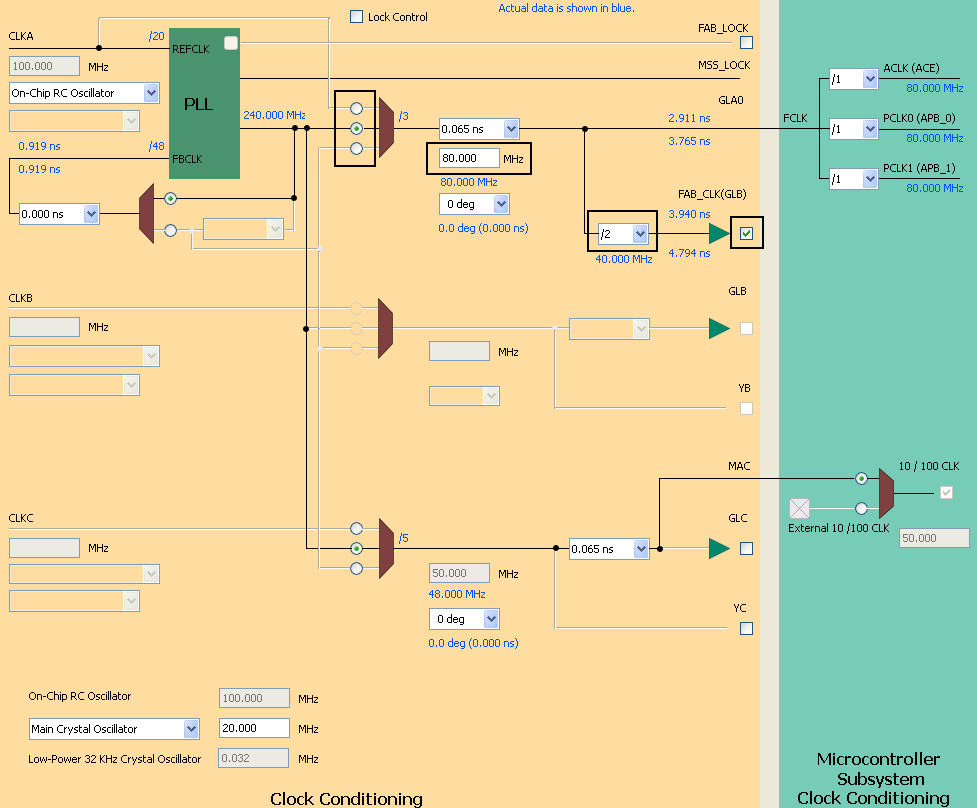
Don't worry, we don't understand all the settings either. The SmartFusion uses these complex clock dividing and conditioning settings for professional users that need a great degree of flexibility.
Next, configure your MSS as shown below (click to see larger version)
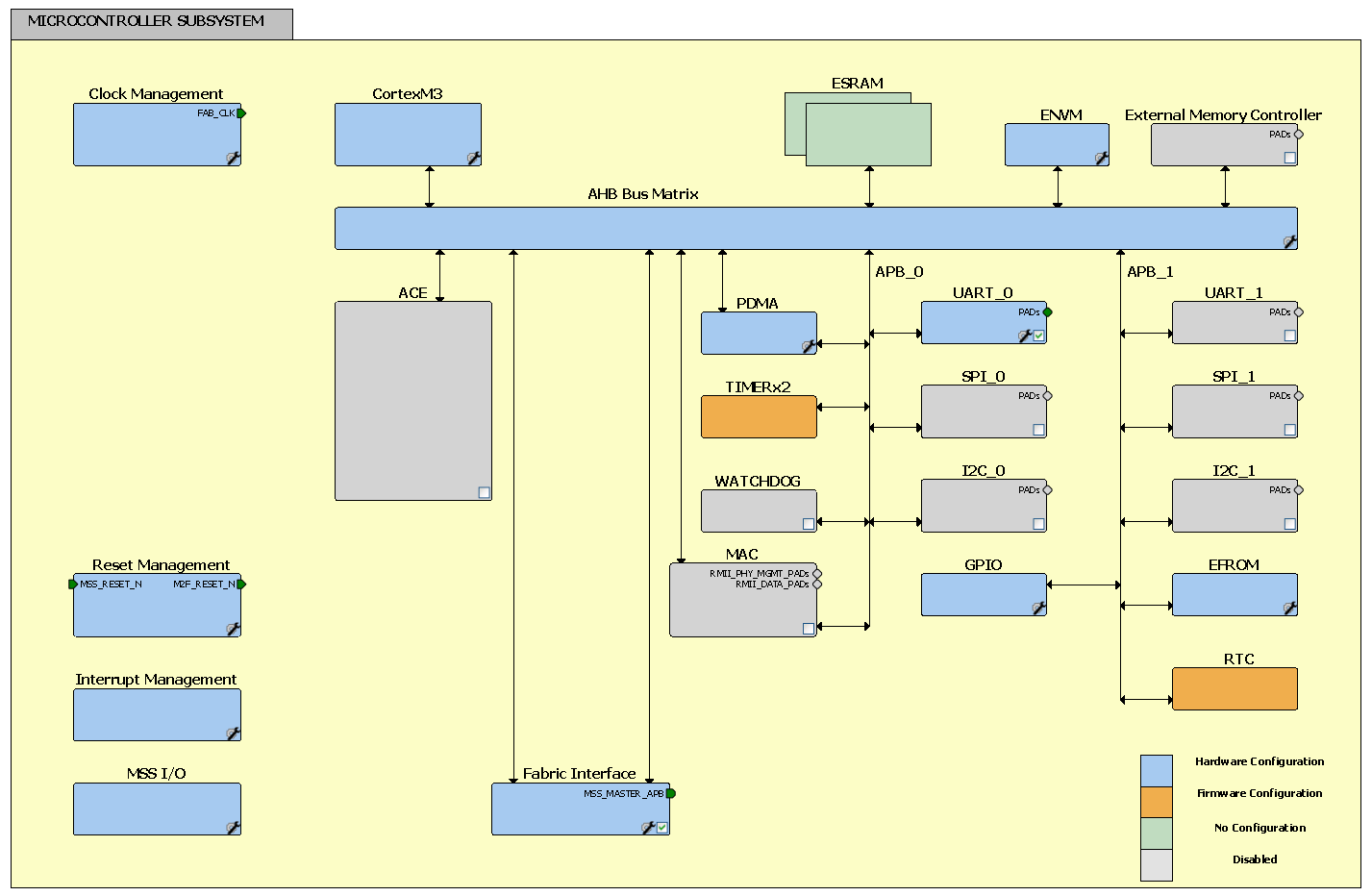
Don't forget to add the APB master interface (MSS_MASTER_APB) and the MSS2FABRIC (M2F_RESET_N) reset. We will add some more components later, once we need them.
On the Firmware tab, generate drivers for,
 .
.
Next, create a new canvas (SmartDesign Component) called lab5_top and make it root. Add the MSS you created above and add a CoreAPB3 Bus Interface to your top level design with 1 slot and 32-bit data bus width. The following timer we create will use this slot.
The last part for the FPGA is the actual timer block and its wrapper. Use the following verilog timer component to start with. SmartDesign > Verilog Source File.
// timer.v
module timer(
			pclk,
			nreset,
			bus_write_en,
			bus_read_en,
			bus_addr,
			bus_write_data, //data_in
			bus_read_data //data_out
            );

input pclk, nreset, bus_write_en, bus_read_en;
input [7:0] bus_addr;
input [31:0] bus_write_data;
output reg [31:0] bus_read_data;

reg [31:0] overflowReg;
reg [31:0] counterReg;
reg [31:0] controlReg;
reg [31:0] nextCounter;
reg overflowReset; // Resets counterReg when new overflow value is written

wire timerEn;   // Timer Enable

//Control Bits
assign timerEn = controlReg[0];

always@(posedge pclk)
if(~nreset)
  begin
    overflowReset <= 1'b0;
    controlReg <= 32'h00000000;
    overflowReg <= 32'h00000000;
  end
else begin
	if(bus_write_en) begin : WRITE
		case(bus_addr[3:2])
            2'b00: // Timer Overflow Register
                begin
                overflowReg <= bus_write_data;
                overflowReset <= 1'b1;
                end
            2'b01: // Timer Value, Read Only
                begin
                overflowReset <= 1'b0;
                end
            2'b10: // Timer Control
                begin
                controlReg <= bus_write_data;
                overflowReset <= 1'b0;
                end
            2'b11: // Spare
                begin
                overflowReset <= 1'b0;
                end
        endcase
    end
	else if(bus_read_en) begin : READ
         case(bus_addr[3:2])
	    	2'b00: // Timer Overflow register
                begin
		        bus_read_data <= overflowReg;
				end
            2'b01: // Timer Value, Read Only
                begin
                bus_read_data <= counterReg;
				end
            2'b10: // Timer Control
                begin
                bus_read_data <= controlReg;
			    end
            2'b11: // Spare
                begin
                end
          endcase
     end
	 else
		overflowReset <= 1'b0;
end

assign timerEn = controlReg[0];

always@*
    nextCounter <= counterReg + 1;

always@(posedge pclk)
if(~nreset) begin
	counterReg <= 32'h00000000;
end
else begin
    if(overflowReset) begin
		counterReg <= 32'h00000000;
	end
    else if(timerEn) begin
		if(counterReg == overflowReg)
			counterReg <= 32'h00000000;
	    else
		    counterReg <= nextCounter;
    end
end

endmodule
// timerWrapper.v
module timerWrapper(// APB Bus Interface
					PCLK,
					PENABLE,
					PSEL,
					PRESETN,
					PWRITE,
					PREADY,
					PSLVERR,
					PADDR,
					PWDATA,
					PRDATA,
					// Test Interface
					TPS);

// APB Bus Interface
input PCLK,PENABLE, PSEL, PRESETN, PWRITE;
input  [31:0] PWDATA;
input  [7:0] PADDR;
output [31:0] PRDATA;
output PREADY, PSLVERR;

// Test Interface
output [4:0] TPS; // Use for your debugging


assign BUS_WRITE_EN = (PENABLE && PWRITE && PSEL);
assign BUS_READ_EN = (!PWRITE && PSEL); //Data is ready during first cycle to make it availble on the bus when PENABLE is asserted

assign PREADY = 1'b1;
assign PSLVERR = 1'b0;

timer timer_0(	.pclk(PCLK),
			    .nreset(PRESETN),
			    .bus_write_en(BUS_WRITE_EN),
			    .bus_read_en(BUS_READ_EN),
			    .bus_addr(PADDR),
			    .bus_write_data(PWDATA),
			    .bus_read_data(PRDATA)
			);

endmodule
Go through the timer code.
Finish your FPGA design by wiring up the timer as shown below. Note that we
didn't connect the TPS signals to anything. If you wish, connect them to
the 5 user I/O lines of the eval board. They can become handy to debug your
code later on. If you don't use them then mark the connection as unused by
right-clicking the signal name.
Check and generate the canvas view .
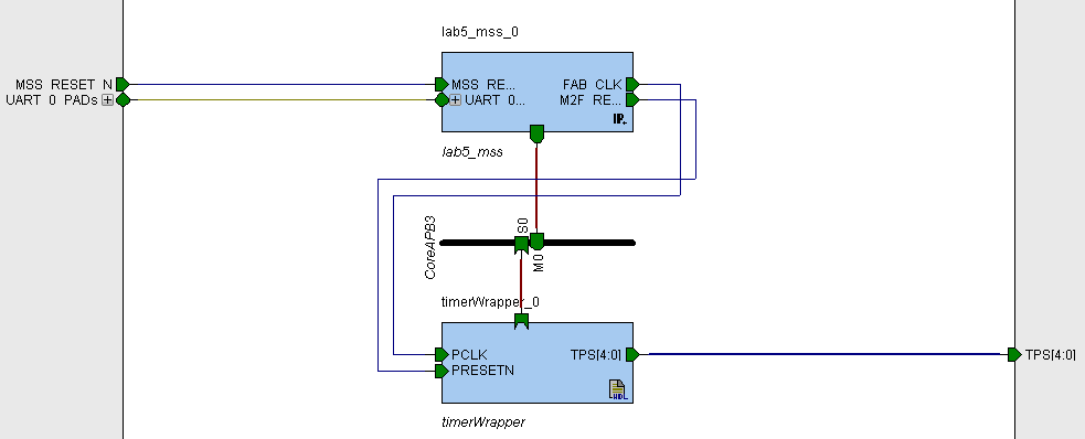
Note that we connected the FAB_CLK to the bus interface's
PCLK.
Our timer is still very simple and has only 3 registers defined:
| Offset | Type | Reset State | Name | Description |
|---|---|---|---|---|
| 0x0 | Read/Write | 0 | overflowReg | Timer counter gets reset (to 0) when it reaches the overflow value |
| 0x4 | Read | 0 | counterReg | Timer Counter Value |
| 0x8 | R/W | 0 | controlReg | Timer Control Bit 0: Enable bit (timerEn) |
The control bit 0 enables or disables the incrementing counter. When
enabled, the counter will increment up to the value stored in the
overflowReg register. Once reached, it resets to 0 and starts counting
again. The counterReg register contains the current value of the
counter.
Now it's time to generate your smart design , synthesize it, place and route
it, and then program your FPGA with it.
We will now write a simple timer library that you can use in your application. Create a new SoftConsole C Project and import the CMSIS and drivers folders from the firmware directory.
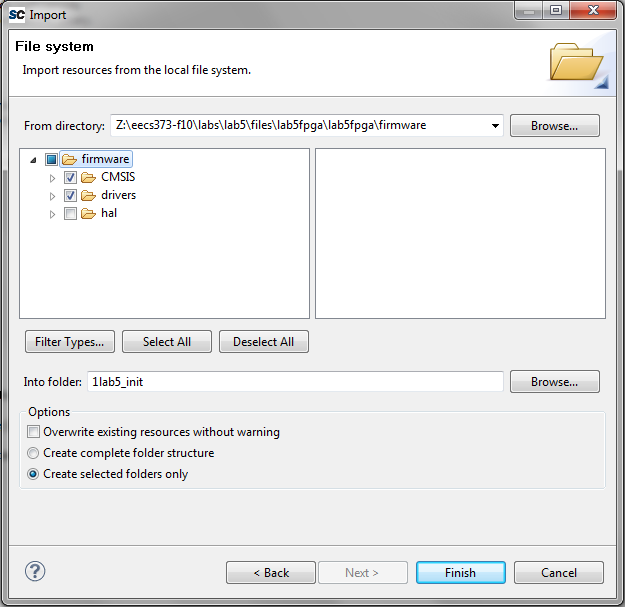
Your Project Explorer should look like this now:
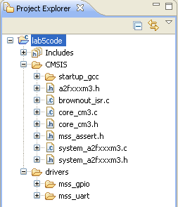
The drivers folder contains the UART_0 and GPIO that you generated in Libero. The CMSI folder contains the different linker scripts as well as startup code for the Cortex-M3. The provided linker script and startup code is far more comprehensive than the one we have been using. While our initial handwritten examples worked, we left out many of the indirections and complexities of properly booting an embedded microcontroller. We will look into this in more detail shortly.
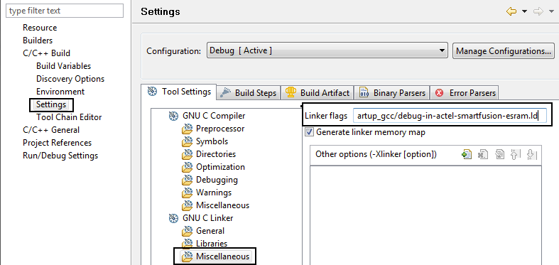
Next, we have to configure our build target. Building is the process of compiling and linking our C source code into the final binary file. For this, right click the Lab2 project and select Properties. Expand the C/C++ Build entry by clicking the arrow left of it. Next, select the Settings entry. This will show several configuration options on the right hand side. In these options on the Tool Settings tab, click on Miscellaneous under the GNU C Linker entry. Set the Linker Flags field to
-T../CMSIS/startup_gcc/debug-in-actel-smartfusion-esram.ld
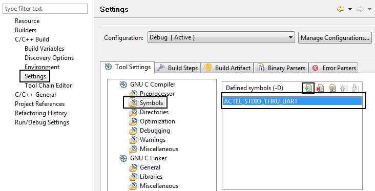
 and add the variable
ACTEL_STDIO_THRU_UART.
For this we will have to import the UART driver
header file. Add the following command to the top of your main.c
file if it doesn't already exist there.
#include "drivers/mss_uart/mss_uart.h"
Now you can use standard printf() statements.
In fact, the printf373() are not setup to work in this project.
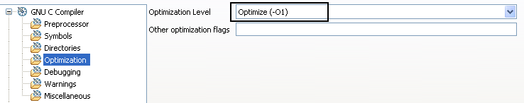
Finally, lets set the -O1 for GCC so that it doesn't generate highly inefficient code and hard to read assembly.
Add new files for main.c, mytimer.c, and mytimer.h.
Following is the content for main.c:
#include <stdio.h>
#include "drivers/mss_uart/mss_uart.h"
#include "mytimer.h"

int main()
{
    /* Setup MYTIMER */
    MYTIMER_init();
    MYTIMER_setOverflowVal((1<<31)); // Set compare to a big number
    MYTIMER_enable();

    while(1)
    {
        uint32_t i;
        printf("Time: %lu\r\n", MYTIMER_getCounterVal()); // Standard printf() now work
        for(i=1e6; i>0; i--); // busy wait
    }
    return 0;
}
Following is the content for mytimer.h:
#ifndef MYTIMER_H_  // Only define once
#define MYTIMER_H_  // Only define once

#include "CMSIS/a2fxxxm3.h"

#define MYTIMER_BASE (FPGA_FABRIC_BASE + 0x0)

// The technique of using a structure declaration
// to describe the device register layout and names is
// very common practice. Notice that there aren't actually
// any objects of that type defined, so the declaration
// simply indicates the structure without using up any store.
typedef struct
{
    uint32_t overflow; // Offset 0x0
    uint32_t counter; // Offset 0x4
    uint32_t control; // Offset 0x8
} mytimer_t;

#define MYTIMER_ENABLE_MASK 0x00000001UL

// Using the mytimer_t structure we can make the
// compiler do the offset mapping for us.
// To access the device registers, an appropriately
// cast constant is used as if it were pointing to
// such a structure, but of course it points to memory addresses instead.
// Look at at mytimer.c
// Look at the the functions's disassembly
// in .lst file under the Debug folder
#define MYTIMER ((mytimer_t *) MYTIMER_BASE)

/**
 * Initialize the MYTIMER
 */
void MYTIMER_init();

/**
 * Start MYTIMER
 */
void MYTIMER_enable();

/**
 * Stop MYTIMER
 */
void MYTIMER_disable();

/**
 * Set the limit to which the timer counts.
 */
void MYTIMER_setOverflowVal(uint32_t value);

/**
 * Read the counter value of the timer.
 */
uint32_t MYTIMER_getCounterVal();


#endif /* MYTIMER_H_ */
Following is the content for mytimer.c:
#include "mytimer.h"

void MYTIMER_init()
{
    // we don't have to do anything.
}

void MYTIMER_enable()
{
    MYTIMER->control |= MYTIMER_ENABLE_MASK;
}

void MYTIMER_disable()
{
    MYTIMER->control &= ~MYTIMER_ENABLE_MASK;
}

void MYTIMER_setOverflowVal(uint32_t value)
{
	// Yes it's inefficient, but it's written this way to
	// show you the C to assembly mapping.
    uint32_t * timerAddr = (uint32_t*)(MYTIMER);
    *timerAddr = value; // overflowReg is at offset 0x0
}

uint32_t MYTIMER_getCounterVal()
{
	// Yes it's inefficient, but it's written this way to
	// show you the C to assembly mapping.
    uint32_t * timerAddr = (uint32_t*)(MYTIMER);
    return *(timerAddr+1); // counterReg is at offset 0x4
}
The technique of using a structure declaration to describe the device register layout and names is very common practice. Notice that there aren't actually any objects of that type defined, so the declaration simply indicates the structure without using up any store.
To access the device registers, an appropriately cast constant is used as if it were pointing to such a structure, but of course it points to memory addresses instead. Using a simple structure, we index all the registers available on the timer peripheral. For example, look at the files in drivers/mss_uart. You will see that they follow a similar structure.
Look at the disassembly in <project_name>.lst file in the Debug
folder. Find the assembly that was generated for the
MYTIMER_enable(), MYTIMER_setOverflowVal(uint32_t
value) , and MYTIMER_getCounterVal() functions. Map the
generated assembly back to the C code in the functions.
Don't forget to define the ACTEL_STDIO_THRU_UART to allow
printf to work. See above.
You will also have to add the linker script to the GNU Linker setting of the
project, before you will be able to compile your code.
Put a breakpoint on the printf function line in main and restart the debug session. Invoke the
instruction stepping feature. Resume the debugger. You will notice that the for loop does not exist
in the disassembled code. The C optimizer (-O1 flag) notices that the loop variable i is not
used after it is incremented, therefore it gets rid of the i and the for loop
that goes with it.
You can trick to compiler into keeping i by declearing it to be volatile. Add the volatile keyword before
uint32_t i;. It tells the compiler to
not make assumptions about i, because it can be used outside of the for loop. Try making the variable volatile.
Read through How to Use C's volatile Keyword.
Connect the serial terminal application to the serial port of the eval board. You should now see numbers being printed on your terminal.
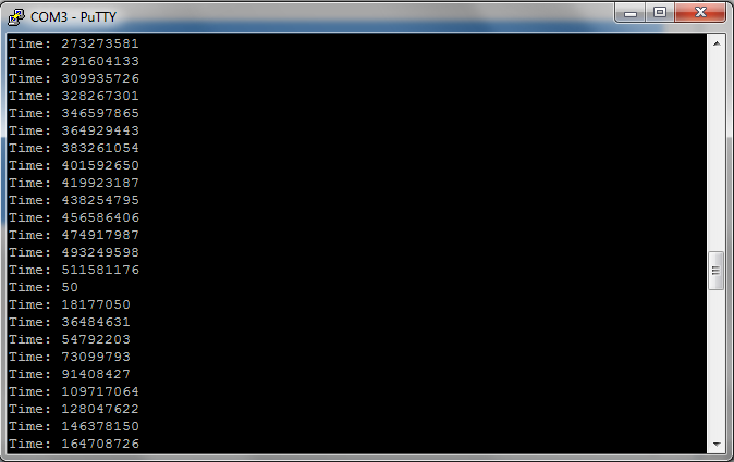
Q: You can see that the numbers overflow after a certain amount of time. Measure that time using a stop watch and calculate the clock frequency. Write down your result. Does it agree with the frequency specified in the MSS Configurator Clock Manager block? Explain in two sentences.
So far, your timer unit provides you time through a software interface. We will now add some more functionality. One of the basic functions of a timer is a timed interrupt. You program the timer unit with a specific time, and an interrupt will fire upon reaching that time.
In the last lab, you learned how to create interrupts on the FPGA, and how to process them in the interrupt service routine. Let's add two interrupt sources to our timer, both sharing the same interrupt line FABINT. An interrupt register will indicate in software which interrupt actually fired. This is very similar to the last lab where we had two interrupt sources, the two switches, sharing the FABINT interrupt line.
The two interrupt sources should fire when the timer reaches two specific values:
Overflow valueCompare value that is less than
the overflow value.Compare value.
Together with the interrupts, we will also need some more control bits
In summary, we will make the following modifications to the code:
We perform all but the first step(s) above, use the following verilog code: timerInt.v and timerIntWrap.v. Replace your previous timer.v file with this implementation and update your smart designer correspondingly.
Don't forget to add the FAB_INT to your
MSS component and regnereate!
Now our modified timer has 5 registers:
| Offset | Type | Reset State | Name | Description |
|---|---|---|---|---|
| 0x00 | Read/Write | 0 | overflowReg | Timer counter gets reset (to 0) when it reaches the overflow value |
| 0x04 | Read | 0 | counterReg | Timer Counter Value |
| 0x08 | R/W | 0 | controlReg | Timer Control Bit 0: Timer Enable bit (timerEn) Bit 1: All Interrupts Enable bit (interruptEn) Bit 2: Compare Interrupt Enable bit (compareEn) Bit 3: Overflow Interrupt Enable bit (overflowEn) |
| 0x0c | R/W | 0 | compareReg | Timer Compare Value (only works if less than Overflow val) |
| 0x10 | Read | 0 | interrupt_status | Which interrupt fired? |
Having more functionality in your peripheral necessitates to update your timer driver. Add the following additional functions form this header file to your library. Make sure that the different enable and disable functions really toggle the right bits in the configuration register.:
/**
 * Enable all interrupts
 */
void MYTIMER_enable_allInterrupts();

/**
 * Disable all interrupts
 */
void MYTIMER_disable_allInterrupts();

/**
 * Enable compare interrupt
 */
void MYTIMER_enable_compareInt();

/**
 * Disable compare interrupt
 */
void MYTIMER_disable_compareInt();

/**
 * Set Compare value
 */
void MYTIMER_setCompareVal(uint32_t compare);

/**
 * Enable overflow interrupt
 */
void MYTIMER_enable_overflowInt();

/**
 * Disable overflow interrupt
 */
void MYTIMER_disable_overflowInt();

 /**
  * Interrupt status
  */
uint32_t MYTIMER_getInterrupt_status();
Implement the missing MYTIMER functions in your
timer.c file.
Once implemented, replace your main function with the following
code. Notice that we added the Fabric interrupt handler too:
uint32_t count;

__attribute__ ((interrupt)) void Fabric_IRQHandler( void )
{
    uint32_t time = MYTIMER_getCounterVal();
    uint32_t status = MYTIMER_getInterrupt_status();

	count--;

    printf("Interrupt occurred at %lu FABINT \n\r", time);

    if(status & 0x01)
    {
        printf("Overflow latency %ld\n\r", 0-time);
    }
    if(status & 0x02)
    {
        printf("Compare latency %ld\n\r", (1<<28) - time);
    }
    NVIC_ClearPendingIRQ( Fabric_IRQn );
}

int main()
{
    /* Setup MYTIMER */
    MYTIMER_init();
    MYTIMER_setOverflowVal((1<<28));
    MYTIMER_setCompareVal((1<<27)); // 50% of overflow

    MYTIMER_enable_overflowInt();
    MYTIMER_enable_compareInt();
    MYTIMER_enable_allInterrupts();

    NVIC_EnableIRQ(Fabric_IRQn);

    MYTIMER_enable();

    count = 1e6;

    while(1){
    	if(!count){ // Global variable checking
			// count decremented inside the interrupt service routine
    		MYTIMER_disable(); // Disable after 1e6 interrupts
    	}
    }

    return 0;
}
Do a clean build and program your eval board with the application and connect the serial terminal.
Observe the latency and convert it to seconds, either in your output by
modifying the printf functions, or on paper.
Q: How does the latency compare to the latency measured with the oscilloscope in Lab 4? Explain in two sentences.
Pause the program, turn on Instruction Stepping, and look at the disassembly.
Notice that it is looping at a branch to itself loop:
0x200004e4 <main+82>: b.n 0x200004e4 <main+82>
This is basically the while(1) loop in code. This time the C optimizer
assumed that count cannot change (it cannot make the connection between
count in the interrupt routine and count here.) Therefore, it moves the if(!count)
outside of the while(1) and checks count once. Why do extra work inside
every loop if it makes no difference? Make count volatile, and notice that it gets rid of the self loop. Use instruction stepping to step through the
full loop now. Notice that it loads and checks count every time. Use this knowlege to debug postlab.
This
might help you debug postlab.
Read through How to Use C's volatile Keyword.
We have almost all the pieces together for a Pulse Width Modulated (PWM) signal generator. PWM signals are very common in embedded systems to deliver a variable amount of energy to an end system, such as LEDs, robotic servos, heating plates, etc. There are two parameters to a PWM system: frequency and duty-cycle. The frequency indicates how often we have a positive edge, while the duty-cycle describes the amount of high time vs. low time of the signal, and is usually expressed in percent. For example, a system that has a pulse every second, then stays on high for 100 milliseconds, before going low for 900 milliseconds would have a duty cycle of 10%.
With the timer unit we have, it is really easy to generate a PWM system. We
just have to set a signal to high when we get to the
Compare value, and set it back to low when we reach
Overflow. In that respect, the Overflow value will determine
the period, or frequency, of our signal, while the Compare value
determines the duty cycle. Software writes the period and duty-cycle values
to the Overflow and Compare registers, respectively.
Modify the timer unit and add the PWM output. Add a control register bit that can enable and disable that output. Connect the PWM output to one of the LEDs on your eval board.
Add PWM capabilities to your timer library, and write an application that generates a PWM signal at 100Hz and changes the duty cycle from 0 to 100% over 1 second. Observe the signal on an oscilloscope and the LED. Describe your observation in a few sentences and include a screenshot of the oscilloscope.
The compare capabilities of a timer allow timed events to happen. The Capture capabilities allow the inverse, i.e., they measure the time of external events. As you saw in the last lab, the handling of interrupt service routines can have significant latency and jitter. Thus, we can not just read the time in software once we entered an interrupt service routine. The capture unit instead grabs the current time inside the timer unit and stores it in a register. It then signals to the core using the timer interrupt that a capture happened. The software can then, at its own convenience, read the capture register.
Let's add capture capabilities to our timer unit:
Use the following file as a reference to implement the above capabilities: timerCapt.v and timerWrapCapt.v. Make sure you connect one of the switches to the capture input. Synthesize, place and route, and program the eval board with your new code.
We now have to add the new capabilities to our timer library. Implement the
following new functions in your mytimer.c file.
/**
 * Enable Capture
 */
void MYTIMER_enable_capture();

/**
 * Disable Capture
 */
void MYTIMER_disable_capture();

/**
 * Read the synchronous capture value
 */
uint32_t MYTIMER_get_sync_capture();

/**
 * Read the asynchronous capture value
 */
uint32_t MYTIMER_get_async_capture();
Write a little application that upon pressing the switch outputs the synchronous and asynchronous capture times, including the difference between them.
Q: What do you observe between the synchronous and asynchronous capture values? Explain in a couple of sentences.
Write a small reaction game. At a specific time, using the PWM output, toggle the LED on. The user has to hit the push button when he sees the light turning on. Then, output the time difference between LED toggle and button push on the serial terminal. How good is your reaction time in seconds?
During the timer lecture, we talked about virtualizing a hardware timer in software, such that it can be shared by several software routines. Implement the timer virtualization interface provided during the lecture, and write an application using it. The application should toggle the 8 LEDs. But every LED should toggle at a different rate, and it should be toggled from its own timer handler.
Tips (Read):
Using the notation provided during the timer lecture, your main.c
function should looks something like this. Note that left out the toggling of
LED code and the initialization of your hardware timer from this pseudo code
for brevity reasons:
#include <stdio.h>
#include "drivers/mss_uart/mss_uart.h"
#include "drivers/mss_watchdog/mss_watchdog.h"
#include "myvirtualtimer.h"

void led0() {
    // toggle LED 0
}

void led1() {
    // toggle LED 1
}

...

void led7() {
    // toggle LED 7
}

int main() {
	/* Watchdog Disabling function */
    MSS_WD_disable();

    initTimer();

    startTimerContinuous(&led0, 2000);
    startTimerContinuous(&led1, 32768);
    ....
    startTimerContinuous(&led7, 1e8);


    while(1){}

    return 0;
}
For reference, following is the proposed myvirtualtimer.h file:
#include "CMSIS/a2fxxxm3.h"

typedef void (*timer_handler_t)(void); // Type of Function pointer

struct timer_t
{
    timer_handler_t handler; // Function pointer
    uint32_t        time;
    uint8_t         mode;
    struct timer_t* next_timer;
};


/* initialize the virtual timer */
void initTimer();

/* start a timer that fires (only once) at time t */
// Return status/error from malloc
uint8_t startTimerOneShot(timer_handler_t handler, uint32_t t);

/* start a timer that fires every dt time interval*/
// Return status/error from malloc
uint8_t startTimerContinuous(timer_handler_t handler, uint32_t dt);

/* stop timer with given handler */
// Return status/error from malloc
uint8_t stopTimer(timer_handler_t handler);
And following is a proposed myvirtualtimer.c file including
pseudo code:
#include <stdio.h>
#include "drivers/mss_uart/mss_uart.h"
#include "myvirtualtimer.h"

volatile struct timer_t* current_timer;

void initTimer() {
    //setupHardwareTimer;
    //initLinkedList;
    current_timer = NULL;
}

uint8_t startTimerOneShot(timer_handler_t handler, uint32_t t) {
    // add handler to linked list and sort it by time
    // if hardware timer not running, start hardware timer
}

uint8_t startTimerContinuous(timer_handler_t handler, uint32_t dt) {
    // add handler to linked list for (now+dt), set mode to continuous
    // if hardware timer not running, start hardware timer
}

uint8_t stopTimer(timer_handler_t handler) {
    // find element for handler and remove it from list
}

__attribute__((__interrupt__)) void Timer1_IRQHandler() {
    struct timer_t * timer;
    MSS_TIM1_clear_irq();
    NVIC_ClearPendingIRQ( Timer1_IRQn );
    timer = current_timer;

    if( current_timer->mode == CONTINUOUS ) {
        // add back into sorted linked list for (now+current_timer->time)
    }

    current_timer = current_timer->next_timer;

    if( current_timer != NULL ) {
        // set hardware timer to current_timer->time
        MSS_TIM1_enable_irq();
    } else {
        MSS_TIM1_disable_irq();
    }

    (*timer->handler)(); // (Dereference function pointer and) call the timer handler

    if( timer->mode != CONTINUOUS ) {
        free(timer); // free the memory as timer is not needed anymore
    }
}
This pseudo code uses the MSS System Timer 1 as timed interrupt source. Feel
free to use your own timer implementation from this lab. Or, you can use the
System Timer 1, though you will have to figure out how to initialize it in your
initTimer function.
These files are only a starting point, you will likely need to modify them (heavily) to get your code working. You may choose not to use them at all and start from scratch if you feel that would be easier for you.
You may work with a partner for this assignment. Hand in your answers from the questions asked during the lab. You are to use the following Answer Sheet. You should show your application to a lab staff and get a signature where asked for on the Answer Sheet.