
Copyright © 2010 -
Thomas Schmid,
Matt Smith,
Ye-Sheng Kuo,
and Prabal Dutta.
Compile and install a simple LED blinking application using the ARM Cortex-M3.
In Lab 1 you learned how to program the FPGA side of the Actel SmartFusion. For Lab 2, we will use the integrated ARM Cortex-M3. Because of the extreme flexibility and interconnect potential of the SmartFusion, we will first have to program the FPGA with some wiring. This will allow the Cortex-M3 to access the external GPIO lines connected to the LEDs. For now, download the following Libero Project Lab 2 FPGA Wiring. You will learn more about this project in Lab 3. For now, just program the FPGA with it as you learned in Lab 1.
You will have to synthesise, place and route, and program the FPGA with this project. Here is a quick reminder of the steps you have to perform.
 or choose
SmartDesign->Generate Design... from the menu. A dialog should
appear informing you that the generation was successful. Click
OK.
or choose
SmartDesign->Generate Design... from the menu. A dialog should
appear informing you that the generation was successful. Click
OK.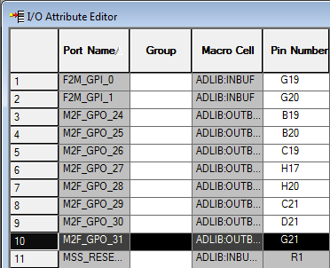

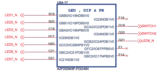
The signal and pin-out configuration is as follows:
First, close any open window. We won't need Actel Libero anymore for the rest of this tutorial, as the Cortex-M3 is programmed using a different toolchain.
Next, we need to create an empty directory that will hold our programming
scripts. Open the command line by clicking on START and type
cmd.exe into the search field. Click on the application that gets
found (in Windows 7 it is a black symbol with a C:\_ inside of
it). The command line should be open now and by default, you should be in your
home directory. Create a new directory by typing
mkdir lab2and hit the
Enter key. To change into the directory, execute
cd lab2Next, we have to setup the environment and let it know where the compiler, linker, and debugger can be found. We accomplish this by adding the Code Sourcery to the PATH environment variable. Type the following into your console
set PATH=c:\Actel\SoftConsole v3.2\Sourcery-G++\bin\;%PATH%Verify that you typed in the right directory and that by executing the make application:
makeThe output should look something like this:
make: *** No targets specified and no makefile found. Stop.If instead you see a message informing you that
make is not a
recognized internal or external command, then verify that the path we typed in
above has the right spelling, and that it really contains the Code Sourcery
tools.
Now we create a simple assembler file with one global labe "main" and a local
label for a branch. Create a file "main.s" with the following content (you can
type start notepad main.s to open the notepad application):
	.global	main
	.type	main, %function
main:
	b	main
	.size	main, .-main
Q: What does this application do?
We now have to compile the assembly file into an object file. We accomplish this by executing the GNU GCC compiler. The created object file will be called main.o, using the input file main.s to create it. Type the following command into the command line:
arm-none-eabi-gcc -mthumb -mcpu=cortex-m3 -O0 -Wall -c -nodefaultlibs -nostartfiles -o main.o main.sThis will execute the arm-none-eabi-gcc compiler. The arguments mean the following:
arm-none-eabi-gcc --help for a general help, or
arm-none-eabi-gcc --target-help for target specific command line
options. A complete list of GCC Command options can be found on the
GCC
Command Options website. There is also more documentation in the Code
Sourcery directory under share/doc/arm-none-eabi/.
If you want to see what the code looks like that gcc generated, you can disassemble it by using objdump as follows:
arm-none-eabi-objdump -S main.oThe output of this program is the disassembled object.
It is now time to link our object into the final binary. We currently have only one object, and thus the linking is trivial. However, in more sophisticated applications, the linker will pull together code from several different objects and libraries to produce one binary output file.
The linker needs an input file to let it know about the memory structure.
Create the following file named link.ld (you can type start
notepad link.ld):
OUTPUT_FORMAT("elf32-littlearm", "elf32-bigarm", "elf32-littlearm")
OUTPUT_ARCH(arm)
ENTRY(main)

MEMORY
{
 /* SmartFusion internal eSRAM */
 ram (rwx) : ORIGIN = 0x20000000, LENGTH = 64k
}

SECTIONS
{
 .text :
 {
   . = ALIGN(4);
    *(.text*)
	. = ALIGN(4);
    _etext = .;
 } >ram
}
end = .;
Next, we link the object file:
arm-none-eabi-gcc -mthumb -mcpu=cortex-m3 -specs=bare.specs -nodefaultlibs -nostartfiles -Tlink.ld -Wl,-Map=lab2.map -o lab2 main.oThis will invoke the linker (note we omitted the -c option to gcc). The new arguments mean the following:
arm-none-eabi/lib.lab2 file
You now have a binary object file. Look at it again using the
arm-none-eabi-objdump application. What do you notice? How is it
different from the output of the main.o file?
We need to change the format of our binary file in order to program the Cortex-M3 with our application. Execute the following commands, one after another:
actel-map -o "memory-map.xml" lab2 arm-none-eabi-gcc -mthumb -mcpu=cortex-m3 -specs=bare.specs -nodefaultlibs -nostartfiles -Tlink.ld -Wl,-Map=.map

arm-none-eabi-objcopy -O ihex lab2  "lab2.hex"

arm-none-eabi-objcopy -O srec lab2 "lab2.srec"

arm-none-eabi-objdump -h -S lab2 > "lab2.lst"
Find out what these specific objcopy commands do by using an Internet search
and the command line arm-none-eabi-objecopy --help command.
We use the GNU Debugger (GDB) to upload our binary to the Cortex-M3. This particular flash application needs a helper application to lock the programmer. Therefore, we have to run an actel keep-alive mutex. Execute the command:
start actel-keepalive actel-keepaliveThis will open a new command window running the actel-keepalive application. Don't close this window, as long as you need GDB. You can, however, minimize it to the taskbar.
Switch back to your other command window and start GDB by typing
arm-none-eabi-gdbThen, execute the following commands. The lines proceeding with a "#" are comments and explaining what the command does:
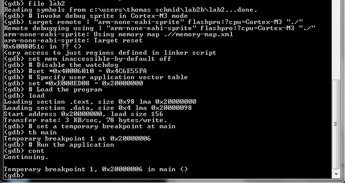
# Load the symbol table
file lab2
# Invoke debug sprite in Cortex-M3 mode
target remote | "arm-none-eabi-sprite" flashpro:?cpu=Cortex-M3 "./"
# Don't restrict memory access to just regions defined in linker script
set mem inaccessible-by-default off
# Disable the watchdog
#set *0x40006010 = 0x4C6E55FA
# Specify user application vector table
set *0xE000ED08 = 0x20000000
# Load the program
load
# Run the application
cont
After the last line, the output of GDB should look like this:
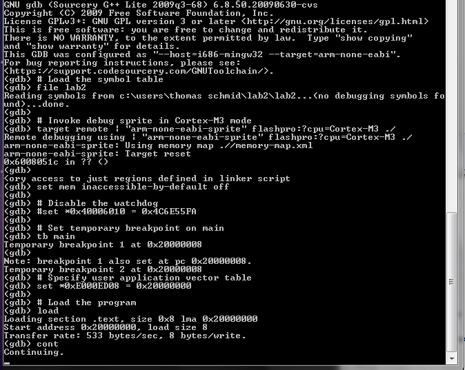
Congratulations. You just started your first application on the Cortex-M3. All the LED's should be lighting up, and the yellow LED D14 should be blinking. Nevertheless, this application is not doing much as it is just busy looping forever.
It's now time to hit ctrl-c to stop the execution. You will again
be presented with the GDB prompt. This prompt allows you to examine the state
of your embedded platform and later on debug your code by looking at variable
values, memory, and registers. Go ahead, type help and explore
some of the capabilities of GDB. For example, type info
registers. However, note that we compiled our code without debugging
information. Thus, some of the commands won't show you any useful information.
Can you tell where in your application you stopped your application if you
type info registers? Explain how and why.
Write some data into registers and perform some math using assembler code. Program the SmartFusion and examine the registers for their values. Did it work?
Write a for loop in assembler by using one of the registers as incrementing variable. Count up to 100 before you go into the busy loop. Can you tell in the debugger if you are still counting, or already in the busy loop? How?
Writing code in assembler can be tricky and difficult. Especially when we have to manage memory, moving to a higher language like C makes a lot of sense. However, we will later see that we can't completely ignore assembly on embedded systems, as C does not capture all the capabilities of the hardware.
In this next example, we will replace our assembler file with a C file. For that purpose, create a new folder by typing:
cd ..
mkdir lab2b
cd lab2b
You will now be in an empty folder called
lab2b. Copy over the
linker file as we can reuse it in this example:
copy ..\lab2\link.ld .
Next, we create the main function. Create a file called main.c
with the following content:
int main() {
    while(1) {}
}
Compile this C file into an object file, without linking
arm-none-eabi-gcc -mthumb -mcpu=cortex-m3 -O0 -Wall -c -nodefaultlibs -nostartfiles -o main.o main.cNote that we replaced the
main.s with the main.c
file. GCC will automatically know that it is a C file and compile it into an
object called main.o
Disassemble the object file using objdump. Do you notice a difference between the assembler file you created and this one?
Next, follow the exact same steps as before for the assembler object:
Verify with GDB that your application runts on the Cortex-M3!
We now change our C application to toggle the I/O lines connected to the LEDs. We accomplish this by using one of the peripherals of the Cortex-M3, the "General Purpose I/O Block (GPIO)". You can find more about this particular peripheral in the "Actel SmartFusion Microcontroller Subsystem User's Guide". You will also learn more about how we really communicate with peripherals in later lectures and labs. For now, it is enough if you understand that if we write at a particular memory location, that data gets transfered to the peripheral and either configures it, or executes some action.
In the case of the GPIO peripheral, we have two specific memory locations of interest. The first one is the configuration register. Note that these are not like the Cortex-M3 registers r0-r15. We just use the name register to indicate a specific location in memory. The microcontroller subsystem has 32 I/O lines, and each line has its own configuration register. The memory location starts at 0x40013000 for I/O line 0 (GPIO0). Each register is 32 bit long, and since the memory is byte indexed, we increment this memory location by 4 to find the configuration register for the other I/O lines, i.e., the configuration register for GPIO i is at (0x40013000 + i*4).
The bits in the configuration register have a specific meaning. The following table is a summary of the different configuration possibilities. To see further description, look at the "Actel SmartFusion Microcontroller Subsystem User's Guide, Revision 1" on page 317.
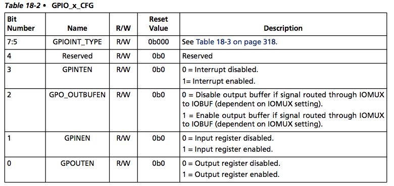
As we want our I/O lines to be output, we will have to write 0x1 into the configuration registers. Once we configured all the I/O lines we need, we can set their status with the output register GPIO_OUT located at 0x40013088. Every bit inside this register represents one I/O line. Thus, clearing bit i to 0, will pull GPIO i low, while setting bit i to 1, will pull GPIO i high.
Alright, let's put this all to use and write a small gpio library. First, we
define the header file for our public functions. Create a file
gpio.h with the
following content:
#ifndef GPIO_H
#define GPIO_H
#include <inttypes.h>

#define GPIO_CFG_BASE 0x40013000
#define GPIO_OUT_BASE 0x40013088

void initGPIO(uint8_t gpio);
void setGPIO(uint32_t out);

#endif //GPIO_H
Next, create the file
gpio.c with the following content:
#include "gpio.h"

uint32_t* GPIO_OUT = (uint32_t*)GPIO_OUT_BASE;

void initGPIO(uint8_t gpio)
{
	uint32_t* cfg = (uint32_t*)(GPIO_CFG_BASE + gpio * sizeof(uint32_t));
	*cfg = 0x01;
}

void setGPIO(uint32_t out)
{
	*GPIO_OUT = out;
}
Now, as before, create the binary object by compiling the gpio.c file using
arm-none-eabi-gcc -mthumb -mcpu=cortex-m3 -O0 -Wall -c -nodefaultlibs -nostartfiles -o gpio.o gpio.c
What is the purpose of the gpio.h file? Disassemble the gpio.o
file and look at the assembly. Do you see anything related to the
gpio.h file? Explain.
Next, it is time to use our gpio library in our main function. Create a new
file called main.c with the following content:
#include "gpio.h"

int main()
{
	uint32_t gpio_status = 0;

 	/* Soft Reset Register */
 	uint32_t * SYSREG_SOFT_RST_CR = (uint32_t *)(0xE0042030);
 	/* Reset GPIO hardware */
 	*SYSREG_SOFT_RST_CR |= 0x00004000;
 	/* Take GPIO hardware out of reset */
  	*SYSREG_SOFT_RST_CR &= ~(0x00004000);

	initGPIO(24);
	setGPIO(gpio_status);

	for(;;)
	{
		gpio_status ^= (1<<24);
		setGPIO(gpio_status);
	}

	return 0;
}
Note that we also have to reset the GPIO peripheral before we can use it. This
is performed by writing 0, then 1 into a particular bit of the
SYSREG_SOFT_RST_CR registers.
Now, as before, create the binary object by compiling the main.c file using
arm-none-eabi-gcc -mthumb -mcpu=cortex-m3 -O0 -Wall -c -nodefaultlibs -nostartfiles -o main.o main.c
Disassemble the main.o file. Do you see the function call into your gpio.o file? Explain.
We now have two object files and are ready to use the linker to create one large binary file. Execute the linker using the following command
arm-none-eabi-gcc -mthumb -mcpu=cortex-m3 -specs=bare.specs -nodefaultlibs -nostartfiles -Tlink.ld -Wl,-Map=lab2b.map -o lab2b main.o gpio.oNote that this time, we have two object files after the
-o lab2b
parameter. You can again disassemble this file and look at the binary code created. Do
you see how the linker resolved all the jumps to the right memory locations in
your main application?
As before, create the auxiliar files from this lab2b binary and
program your SmartFusion evaluation board using GDB.
Is LED 1 really permanently turned on? Verify using an oscilloscope to see if LED 1 is really turned on continuously. What is the frequency of the signal that you see? How does this related to the CPU clock frequency?
Modify your code with a for loop to wait between LED toggles. Make the LED toggle every 1 second.
Extend your main function to include all LEDs. Toggle each LED at different frequencies, e.g. 128Hz, 64Hz, 32Hz, 16Hz, 8Hz, 4Hz, 2Hz, 1Hz.
You already know how to launch GDB. However, its usefulness in order to find
information about the running application were fairly limited so far. The
compiler has to annotate your binary with special information in order to let
GDB know more about the application. We accomplish this by passing the
-g option to GCC.
Recompile your gpio application but add -g to every call of GCC,
i.e., execute the following commands
arm-none-eabi-gcc -mthumb -mcpu=cortex-m3 -O0 -g -Wall -c -nodefaultlibs -nostartfiles -o gpio.o gpio.c

arm-none-eabi-gcc -mthumb -mcpu=cortex-m3 -O0 -g -Wall -c -nodefaultlibs -nostartfiles -o main.o main.c

arm-none-eabi-gcc -mthumb -mcpu=cortex-m3 -specs=bare.specs -nodefaultlibs -nostartfiles -Tlink.ld -Wl,-Map=lab2b.map -o lab2b main.o gpio.o
Disassemble the lab2b binary now. Do you notice the difference to before?
Now, let's start GDB but this time, use the following script to run your application
# Load the symbol table
file lab2b
# Invoke debug sprite in Cortex-M3 mode
target remote | "arm-none-eabi-sprite" flashpro:?cpu=Cortex-M3 "./"
# Don't restrict memory access to just regions defined in linker script
set mem inaccessible-by-default off
# Disable the watchdog
#set *0x40006010 = 0x4C6E55FA
# Specify user application vector table
set *0xE000ED08 = 0x20000000
# Load the program
load
# set a temporary breakpoint at main
tb main
# Run the application
cont
Note that this time, we set a temporary breakpoint. Once you hit enter after
cont GDB will stop once it reaches the main function. Your GDB
shell should look something like this:
You are now ready to debug your application. The following list are some useful GDB commands. But they are by far not all of them. Use the GDB help for many more commands to inspect memory, backtrace code, or for different types of stepping or continuing executing the code.
| cont | continue execution until the next breakpoint |
| step | advance to the next line of code |
| step n | advance n code lines |
| next | step forward proceeding through subroutine calls |
| b main.c:16 | set a breakpoint on line 16 in the main.c file |
| b setGPIO | set a breakpoint at the beginning of the setGPIO function |
| list | show the source code around the current position |
| disp varname | display the content of variable varname every time we stop |
| bt | backtrace the function call history |
There are many many more commands in GDB. I encourage you to learn how to use
GDB, as it is THE tool for debugging your embedded system. For example, you
can put a watch on a variable, and interrupt the program code if the
variable, or memory location for that matter, changes. Also note that hitting
enter on an empty line in GDB repeats the last command. This is
extremely useful if you just want to step through code and advance one line at
a time.
Try out to set a breakpoint at the setGPIO function entry. Then, continuously
execute the program and observe how the LED toggles every time you continue.
Also, try to find out what the difference between b and
bt breakpoints is.
Explain the difference between the GDB commands step and
stepi. Use the GDB help command to find the
difference.
As you can see from the GPIO mappings at the beginning of this tutorial, GPIO 0 and 1 are mapped to the two switches SW1 and SW2. Extend your gpio library to configure the GPIO's also as input by adding a parameter to the init function. Additionally, add a function to read the status of the GPIO lines from the GPIO_IN register at address 0x40013084 and show the status of these I/O's on two of the LEDs.
GCC can automatically optimize your code for better performance. Try to pass
-O1, -O2, or -Os instead of
-O0 and look at the generated assembly and debug information. It
can very well happen that the optimization removes some of your C commands,
and thus debugging can become very tricky and difficult. One more reason to
know some assembly.
Until now, you have done everything by hand, and embedded system programming might seem tedious to you. However, there exist very good Integrated Development Environments (IDE) that wrap all the tools you just used into a nice interface.
Actel's development IDE is called SoftConsole and is based on
Eclipse.
Underneath, it uses the CodeSourcery G++ for the exact same steps you just
executed. They just hide them using a nice interface. Additionally, they use
make, a tool which controls the generation of executables and
other non-source files. However, it is beyond the scope of this class to show
you everything that GNU make can do, especially as SoftConsole completely
hides its usage. If you are interested, read the GNU Make Website
or ask a TA or lab staff for the location of the Makefile. We are happy to
show you where it is.
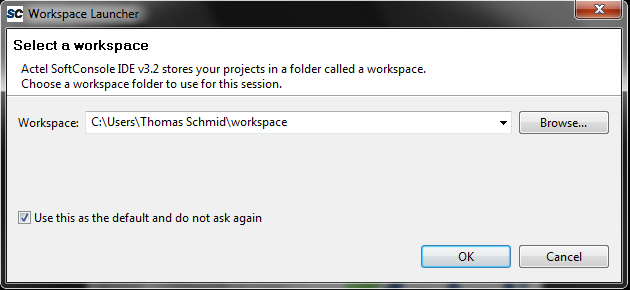
You can close all the open windows, and start SoftConsole through the Start Menu. After starting, SoftConsole will ask you for the workspace. Accept the default, mark the "Use this as the default and do not ask again" checkmark, and hit OK.
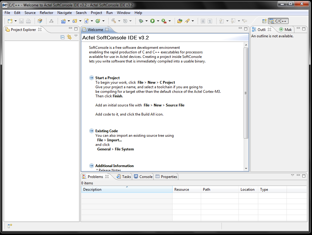
Next you will see the "C/C++ Prespective". This is the layout for C or C++ development.
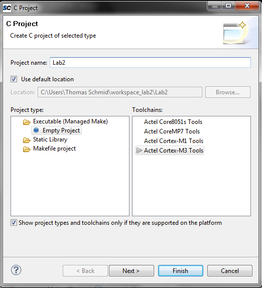
We first have to create an empty project. Click on File > New > C Project. Name the project Lab2 and make sure the Actel Cortex-M3 Tools Is selected in the Toolchains choice. Then hit finish.
Now we are ready to create our first C source file. Click on File > New > Source File. Name the file main.c and make sure that it says Lab2 Source Folder. When done, hit Finish.
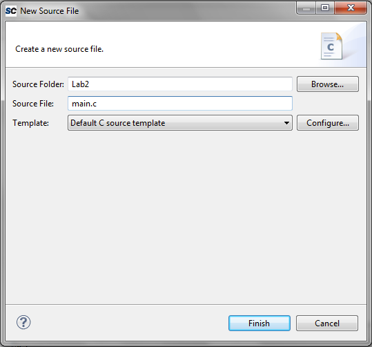
Now, copy the content from your last main.c file into this one.
If you want, you can keep the comment at the top of the file. Note that the
IDE immediately notices that you don't have a gpio.h file in your
project yet. We will import these files in the next step.
To import the gpio.c and gpio.h files, right click
on the Lab2 project name on the left hand side and select
Import.... In the lower selection list, select General > File System
and click Next. Click on Browse... and select the lab2b
folder under your user name. After hitting Ok you should now see the
content of this folder in the lower selection window. Select the
gpio.c and gpio.h files and click Finish.
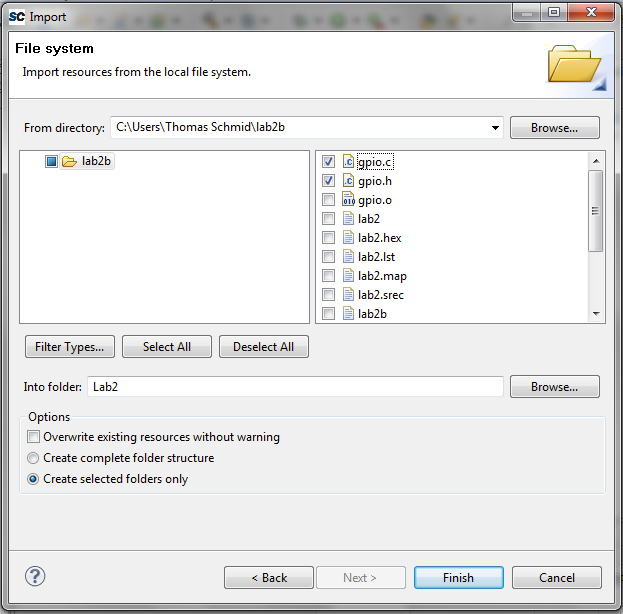
Notice how the question mark before gpio.h dissapeared.
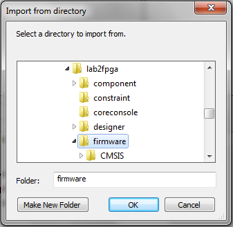
Now, we have to import some pre-generated files from the FPGA side. As before, right click the Lab2 project name on the left hand side and select Import.... Locate the lab2fpga directory from the beginning of this lab. It is most likely in your download folder. Inside lab2fpga select the firmware folder and click OK.
Select the CMSI folder by expanding the firmware folder on the left hand side. Then, click Finish.
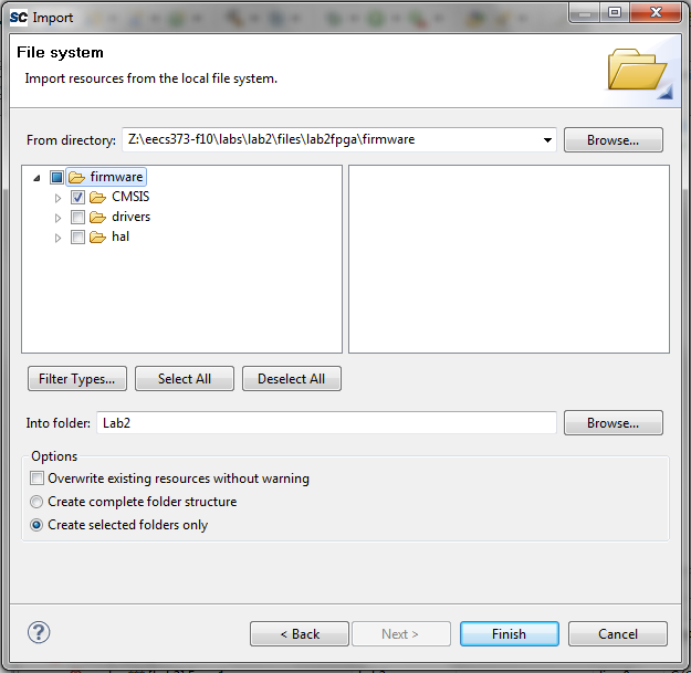
The CMSI folder contains the different linker scripts as well as startup code for the Cortex-M3. While our initial handwritten examples worked, we left out many of the indirections and complexities of properly booting an embedded microcontroller. We will look into this in more detail shortly.
Next, we have to configure our build target. Building is the process of compiling and linking our C source code into the final binary file. For this, right click the Lab2 project and select Properties. Expand the C/C++ Build entry by clicking the arrow left of it. Next, select the Settings entry. This will show several configuration options on the right hand side. In these options on the Tool Settings tab, click on Miscellaneous under the GNU C Linker entry. Set the Linker Flags field to
-T../CMSIS/startup_gcc/debug-in-actel-smartfusion-esram.ld
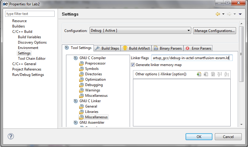
This particular linker script builds an executable that runs from the SmartFusion internal SRAM. Therefore, after a reset, the program will be gone. We will see later how we can program our application into the non-volatile memory of the SmartFusion.
We are now ready to build our project. Click on Project > Clean... and make sure that the Lab2 project is selected. This will remove any old binaries and create the final binary.
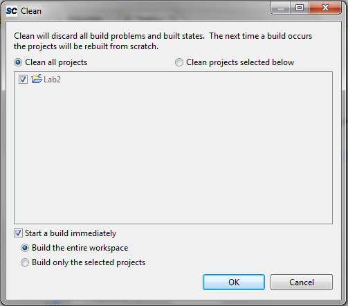
If everything went well, then you should have an empty Problems tab on the bottom of your perspective.
Note that by default, all the binaries build with SoftConsole contain debug information. You will also note that you got two new folders in your project named Debug and Binaries. As their names suggest, they hold debug information and the final binary respectively.
Expand the Debug folder. You will see many familiar files inside of it
that you manually created last time. The key behind everything is the
makefile inside this folder. It tells make what
targets it should compile, and which commands to run.
Now, let's program our microcontroller and start the debugging. The first time, we will have to configure our debug target. For this, right click your project Lab2 and select Debug As > Debug Configurations .... A new window will open. Right click Actel Cortex-M3 RAM Target and select New.
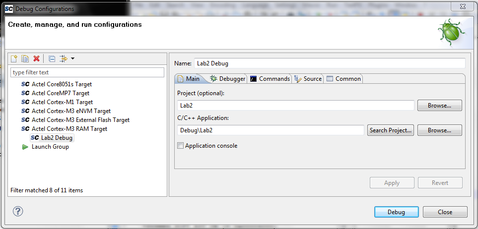
Next, click on Apply then Debug. The window will close and SoftConsole asks you if it should switch over to the Debug Perspective. Click on Remember my decision. Then click on Yes.
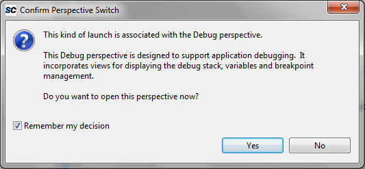
SoftConsole automatically launched GDB in the background. You can see its output in the bottom Console tab. Additionally, SoftConsole's Debug Perspective also shows you your source code, an outline of your binary, variables, breakpoints, registers, and a call trace. At the top, it gives you shortcuts to typical GDB commands you used earlier like cont (called resume, the button with the green arrow), step (called step into), next (called step over), and many more.
Try to add a breakpoint by double clicking on the space just left of the line number in your main.c file. Notice how the line gets marked with a green dot, and how the breakpoint appears in the Breakpoint tab. Click the Resume button (or hit F8). Notice how your code stopped on your breakpoint. Additionally, the Variables tab updated to the current context, showing your the content of all the visible variables.
If you ever feel the need that C stepping doesn't work, and that you need to look at the disassembled code, click the Instruction Stepping Mode button on the top (the letter "i" with a right pointing arrow). A new tab will appear showing you the disassembled code at your location. Additionally, the step button now becomes a stepi instruction. You can also add breakpoints to the disassembly tab, similar as you were able to do in the C file.
Explore the capabilities of the debugger. I highly encourage you to learn the keyboard shortcuts. They will make your life much easier later on during the projects. Additionally, it speeds up your debugging a lot.
Sometimes it is necessary to write just a few lines of assembler in your C files. In this case, we can use GNU GCC's inline assembly feature. For more details, see the following page:
ARM GCC Inline Assembler Cookbook
The following is a small example on how to use inline assembly to access
variables in C. Replace your main.c file with the following:
#include <inttypes.h>
#include "gpio.h"

int main()
{
    uint8_t i;
    uint32_t a, b;
    uint32_t * P_WDG_ENABLE = (uint32_t *)(0x40006010);

    /* Disable Watchdog Timer*/
    *P_WDG_ENABLE = 0x4C6E55FA;

    for(i=24; i<32; i++)
    	initGPIO(i);
    setGPIO(0xFFFFFFFF);

    a = ~0x01;

    while(1)
    {
    	asm("mov %[result], %[value], ror #1" : [result] "=r" (a) : [value] "r" (a));
    	setGPIO(a);
    	for(b=1e6; b--; b>0);
    }

    return 0;
}
Explain what this application does and how the C values get passed to the inline assembly function. Hint: use the disassembly function of Soft Console.
Inline assembly has many applications in embedded systems. For example, there are many assembler commands that don't have a corresponding C function. One such example is the "Wait for Interrupt" or WFI instruction. This instruction puts the processor into sleep, and waits until an interrupt arrives. We will see in Lab 4 how this function gets used in an application. Other times, a core might provide an optimized command set for math or signal processing. GCC often times doesn't know how to use these commands, and thus won't optimize your C code. In these cases, inline assembly can help to create faster code.
In the last part of this lab, we will have a closer look at the boot sequence used in SoftConsole. While the code we earlier wrote worked and executed on the SmartFusion, the boot sequence we used is incomplete. We left out many of the details necessary to properly start up a modern microcontroller. But why haven't you seen any additional scripts? It turns out that SoftConsole hides most of this complexity from the regular user. But, it is still possible to dig into it and see where all the data comes from.
Let's start at the beginning, in the linker script. Go back into the C/C++ perspective and expand your Lab2 folder. Next, expand the CMSIS folder, and then the startup_gcc folder. Remember this location? This is the same path that you entered in the Linker flag in the properties.
Now, double click on the debug-in-actel-smartfusion-esram.ld script. Try to find the parts that you are familiar about from your linker script, and try to find out what the other things do. Most of it is setting up the stack and declaring sections in the binary object where specific parts of code should be placed.
One of the most important statements is the ENTRY(Reset_Handler)
statement. This is where your code starts to execute. But where is this
function defined? Since you didn't write it in your main.c file. Go back to
your SoftConsole window and open up startup_a2fxxxm3.s. This file
contains most of the startup code written in assembler. The first definition
is the vector table, also called interrupt vector. You will learn more about
this in a later lab. For now, scroll down past this section to line 192. This
is the entry function, the Reset_Handler. This is the function
that gets called when your microcontroller comes out of a reset, such as at
boot time or when pushing the RESET button.
Go through the rest of the code. As a Post-Lab Assignment, describe what the
code does, and how it gets to your main function.
Write a simple blinking LED function in Assembler with the following function
signature: void blink(uint8_t num, uint8_t state) where
num is the LED number and state the state the led
should be put in (0: OFF, 1: ON). Put this function into its own object file.
Call this function from within your C code.
We showed you where the Reset_Handler is located. Describe what
this function does, and describe the initialization procedure. On which line
and file do we call our actual main function? Explain.
Create a "Knight Rider" effect with all the LEDs. The LEDs should fade, not just toggle, between each other.
You may work with a partner for this assignment. Submit all C and assembler code as well as a text file containing the answers from the questions asked during the lab, and the post-lab assignment. You can use the following Answer Sheet.