Statistics: 33 inputs; 25 outputs; 880 gates
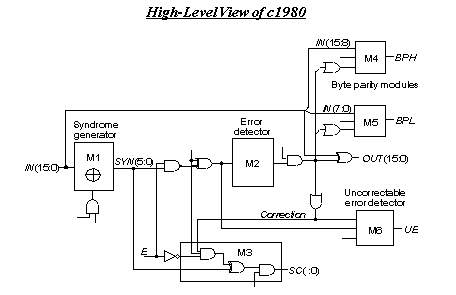
Function: 16-bit error detector/corrector
This is a 16-bit single-error-correcting and double-error-detecting (SEC/DED) circuit with some byte-error detection capability. It generates a 6-bit syndrome from the 16-bit data input IN, which is decoded to find the bit in error, if any. If an error is detected and the control inputs are set appropriately, error correction is performed. c1908 has an output indicating an uncorrectable error; this is set when more than one erroneous bit is detected. The circuit can also generate syndrome bits, which are sent out via the SC lines. The external syndrome lines make it possible to cascade several copies of c1908 so that detection and correction can be done for words of size greater than 16. This circuit is quite similar to the Advanced Micro Devices Am2960 16-bit error detection and correction unit.
Models:
Major Input/Output/Internal Signals:
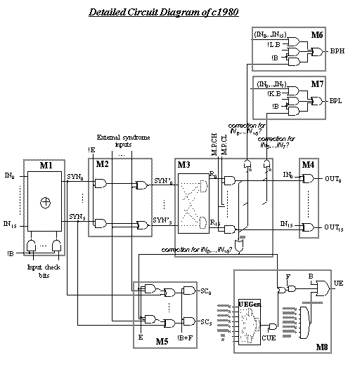
This module generates a 6-bit syndrome (SYN) from the 16-bit input data bus (IN) and 6 input check bits (InCheckBits). The input check bits are modified with the control inputs G and H as follows:
The syndrome bits are calculated according to a modified Hamming matrix shown below.
This module is used to change the 6-bit syndrome (SYN) generated by M1. Its output is called SYN'[5:0] (NewSynBits) that also depends on the control input E, and another bus named AllExtSynBits. The definition of AllExtSynBits[5:0] is as follows:
The AllExtSynBits bus appears to be an external set of syndrome inputs that can override the syndrome (SYN) when E is set to 1. Otherwise the SYN' output is the XNOR of SYN and AllExtSynBits. The ability of c1908 to change the calculated syndrome is probably exercised when it is cascaded to handle words of size greater than 16. When E is set to 0 and AllExtSynBits are all 1's, the syndrome goes through M2 unchanged.
This module consists of 16 AND gates that decode the syndrome bits to identify the erroneous bit, if there is one. It matches the syndrome bits against the columns of the above Hamming matrix. The product term calculated by each AND gate is shown in the following table.
If bit i is in error, then Ri will be set to 1, while all the others are 0. Notice that the rows of the above table are identical to the columns of the modified Hamming matrix.
Module M3 generates three additional signals called CorrectionFlag, CorrectionFlagLo and CorrectionFlagHi that are fed into modules M5, M6, M7 and M8. CorrectionFlag is the OR of R0-R15, which is set to 1 when any bit is in error. CorrectionFlagLo is the OR of R0-R7, which is set to 1 only when the lower byte includes the erroneous bit. Similarly, CorrectionFlagHi is the OR of R8-R15, which is set to 1 only when the upper byte includes the erroneous bit.
Module M8 (UncorrErrorGenerator)
When an error is found in the data input or check bits, this module identifies whether it is an uncorrectable one. For certain cases of multiple errors, correction is not possible, but its occurrence can be signaled so that the problem can be handled by other means. If such a case is found, the output of M8 is asserted. The following term calculated by M8 evaluates to true when there is no error in any bit:
SYN'[0].SYN'[1].SYN'[2].SYN'[3].SYN'[4].SYN'[5].M.P
It is a sub-module named UEGen that detects if there is an uncorrectable error condition. There are 8 cases of uncorrectable error, each of which is calculated by an AND gate. The product terms for these 8 cases are given below.
|
146, 143, 140, 137, 134, 131, 128, 125, 122, 119, 116, 113, 110, 107, 104, 101 |
|