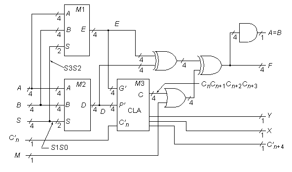
74181 4-Bit ALU/Function Generator

Statistics: 14 inputs; 8 outputs; 61 gates; gate-level schematic
Function: The 74181 can be modeled as above. Recognizing the logic that makes up a CLA block—in this case, the circled elements in the gate-level schematic—is the key step in unraveling the secrets of the 74181. The four boxed circuits in the gate-level schematic are represented above by the single module M1 with 4-bit I/O buses. The second quadruplicated circuit in the 74181 leads to the high-level module M2. The various XOR gates are also grouped into 4-bit word gates as indicated above. Further analysis shows that the 74181’s original designers cleverly constructed the M1 and M2 logic so that with input line M = 1, each setting of the S (function select) bus produces one of the 16 possible Boolean functions of the form F(A,B).
Note: The M line above has been logically moved from within the CLA block M3, to after the block. This was done to make module M3 a standard CLA block. The change preserves the function, but does make subtle differences when analyzing, for example, path delays in the two circuits.
Models: