Building an Intel-Based Platform for Ardupilot
Using the PXFMini with an Intel UP
Kevin Angstadt
angstadt@umich.edu
University of Michigan
Introduction
This tutorial provides step-by-step instructions for developing a Intel-based autonomous vehicle platform running an Ardupilot software stack. Steps include: assembling computation and sensor hardware, building an operating system distribution, and building software on the system. The base system consists of an Intel UP board, which is augmented by the PXFMini autopilot HAT developed by Erle Robotics.
Note: this tutorial is a work in progress. This document will be updated as the build process becomes more refined and bugs are resolved.
Looking for the older build guide? It is still available here.
Known Issues
- RCInput firmware does not always handle no signal correctly
- No ROS
Parts List
The following parts are needed to construct the autopilot:
Intel Up Shop
Erle Robotics
-
1x PXFMini + Additional Components:
- 1x GPS + Compass
MRobotics
- 1x mRo SiK Telemetry Radio V2 915MHz
- 1x mRo 4-Pins JST-GH to 4 Separate 2.54mm Females - MRC0221
- 1x mRo Classic Power Module (BEC) 4S LIPOs (It is also possible to purchase an equivalent part from Erle, but we have found the wire guage to be insufficient.)
Digikey & Mouser
- 2x 40 Position Receptacle Connector 0.100" (2.54mm)
- 2x Round Spacer Unthreaded Nylon 0.100" (2.54mm)
- 6x 11mm M2.5 Male-Female threaded standoff
- 1x ATTiny85
- 1x TinyUSB programmer
- 1x 8 position IC DIP Socket
- 1x 16 position vertical header (male)
OSHPark
- 1x PPM RC Input Circuit Board (A Sparkfun solderable breadboard could be substituted here, but will not fit in the case)
3D Printed Parts
Miscellaneous
- Micro-USB cable
- USB Flash Drive (minimum 4 GB)
- Blue Loctite (threadlocker)
- 4x M3x6 Machine Screws (available at a hardware store or through Bolts Depot)
Construction
Assemble RCInput Circuit Board
For this step, you will need a copy of the Arduino IDE installed and configured to program ATTiny85 microcontrollers. A helpful guide may be found here.
- Solder the 8-position IC DIP socket onto the circuit board
- Break off a 3-pin and a 4-pin section from the 16-position header and solder to the board
-
Clone
PPMSumArduino Sketch repository:git clone git://github.com/kevinaangstadt/PPMSum.git
-
Launch the
PPMSumproject in Arduino. -
Ensure that the following settings are selected in the Tools menu:
- Board: ATTiny25/45/85
- Processor: ATTiny85
- Clock: Internal 16 MHz
- Programmer: USBTinyISP
- Insert the ATTiny85 in the TinyUSB programmer and attach to computer
- Select Tools > Burn Bootloader. Check the error logs to verify that this completes successfully.
- Select Sketch > Upload to flash the firmware. Check the error logs to verify that this completes succesfully.
- Insert the ATTiny85 into the 8-position DIP header on the RCInput circuit board. Be sure to verify correct orientation.
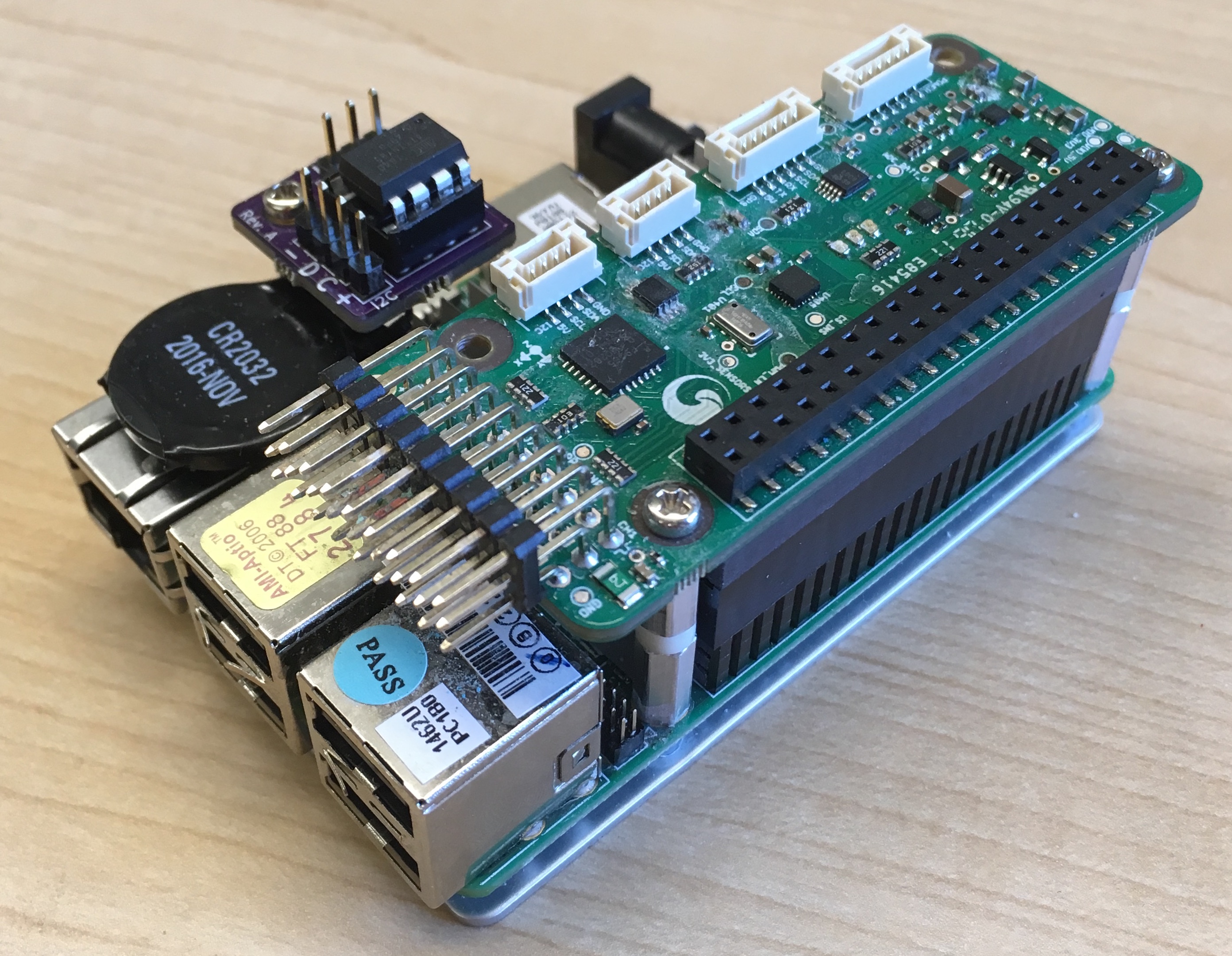
Attach components to the UP Board
- Stack 40-pin headers and connect to GPIO pins of the UP Board
- Remove the two screws attaching the lower heatsink to the UP Board near the GPIO pins
- Attach two standoffs and one spacer (with the spacer between the two standoffs) to both of the screwholes. Use threadlocker to keep everything tight.
- Attach PXFMini HAT to 40-pin header
- Reinstall two removed screws
- Remove the screw attaching the lower heatsink to the UP Board near the ethernet port
- Install two standoffs in this hole. Use threadlocker to keep everything tight.
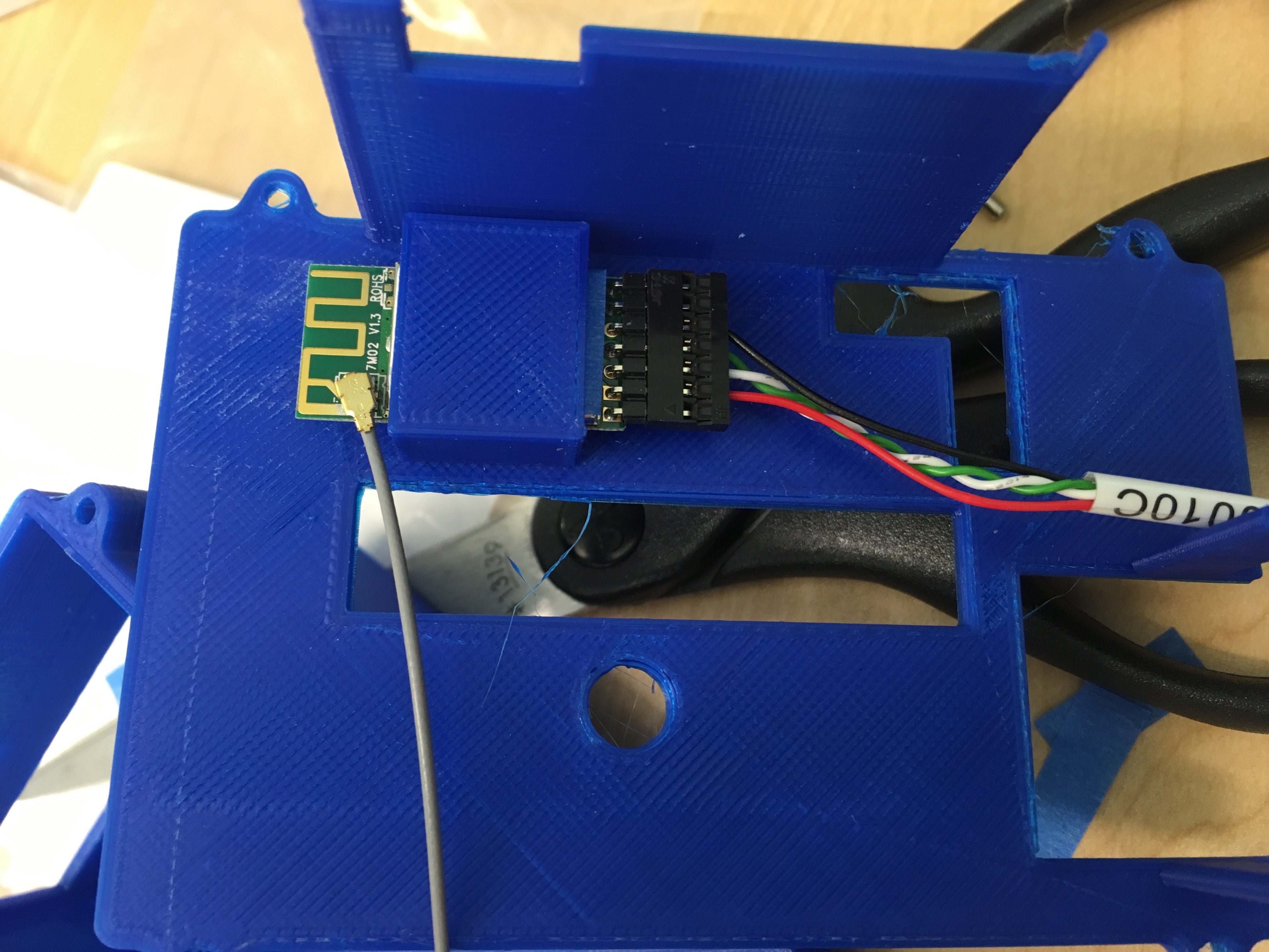
- Attach RCInput circuit board to this standoff using the screw that was previously removed. The three-pin header should be parallel with the long side of the UP.
After this step is complete, the UP Board should look like the following:
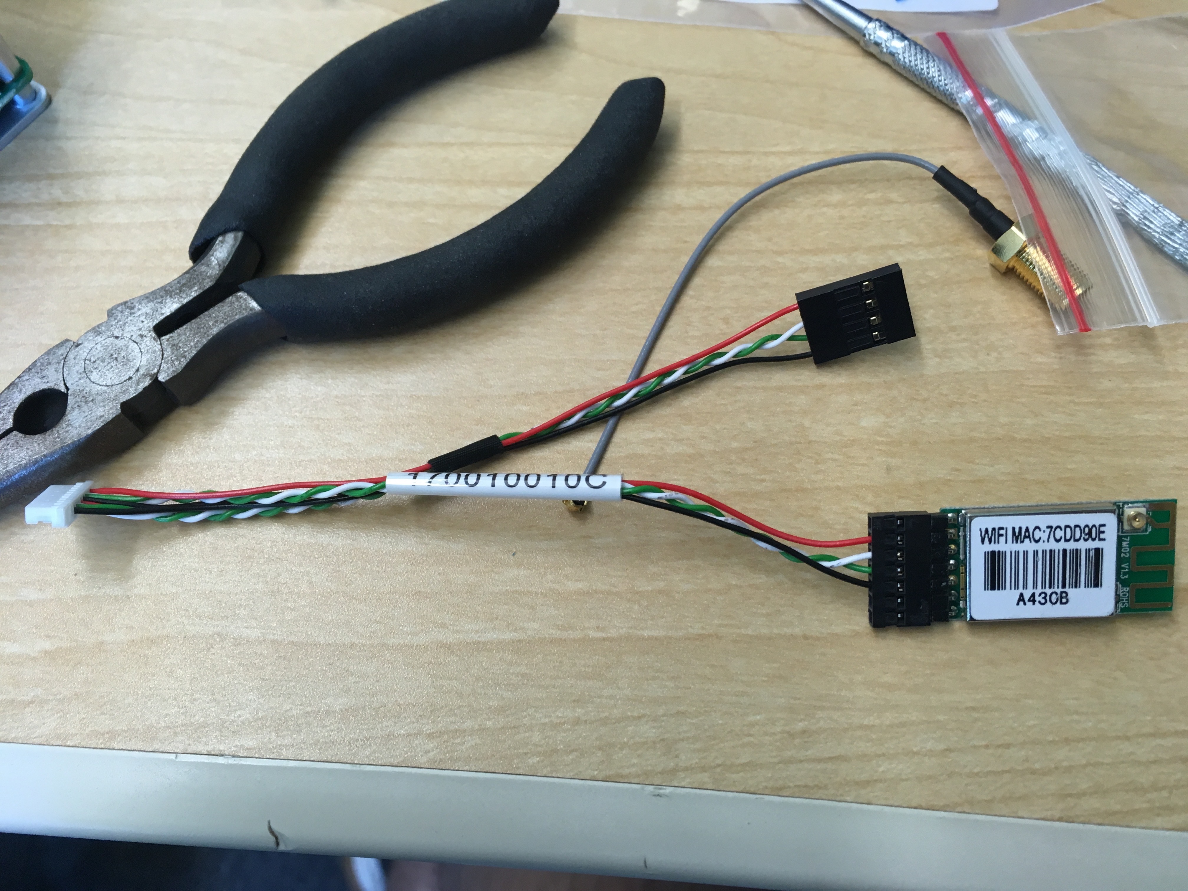
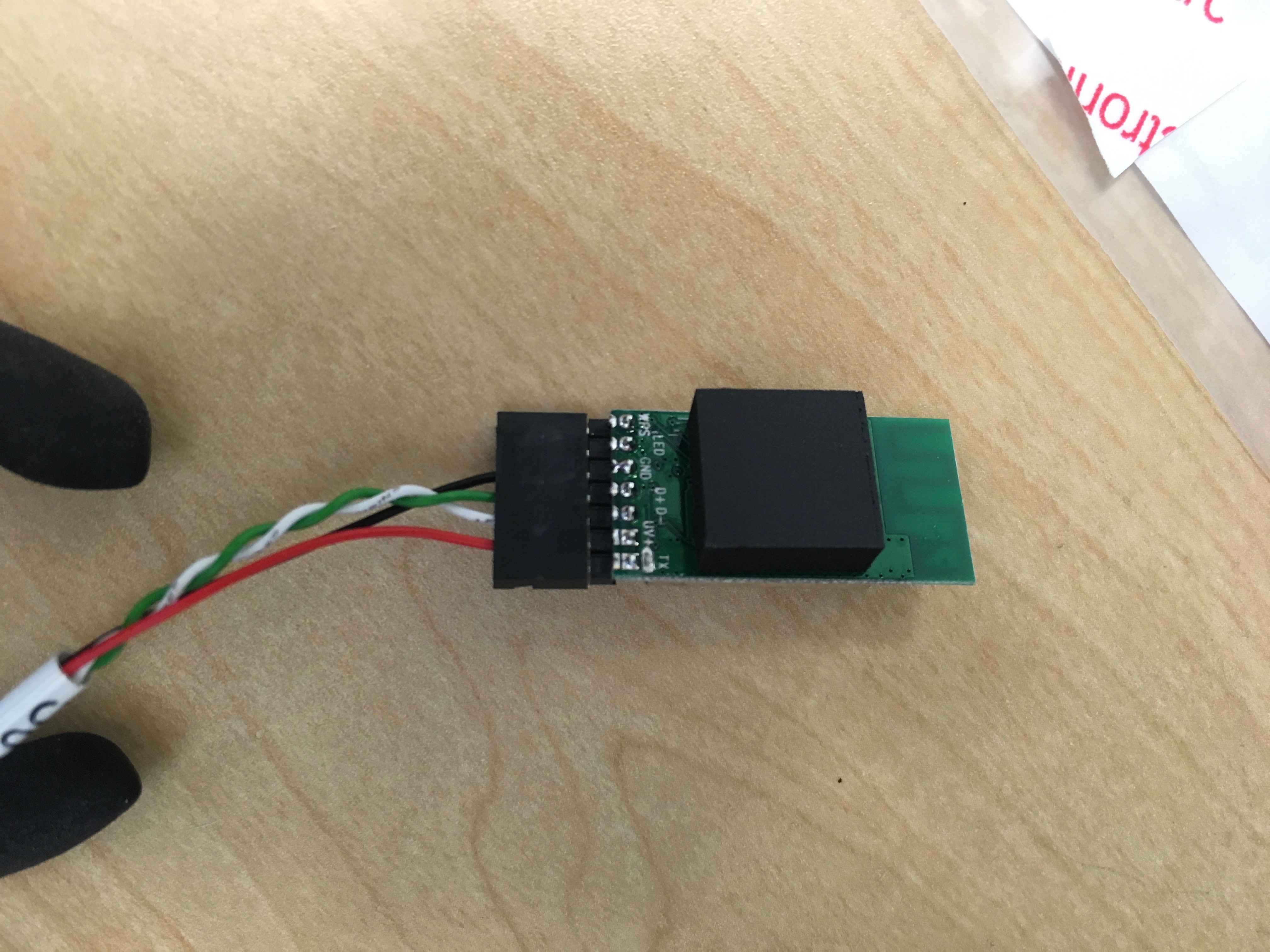
Attach peripherals
-
Assemble and connect the WiFi kit for the UP board following the
instructions in this guide.
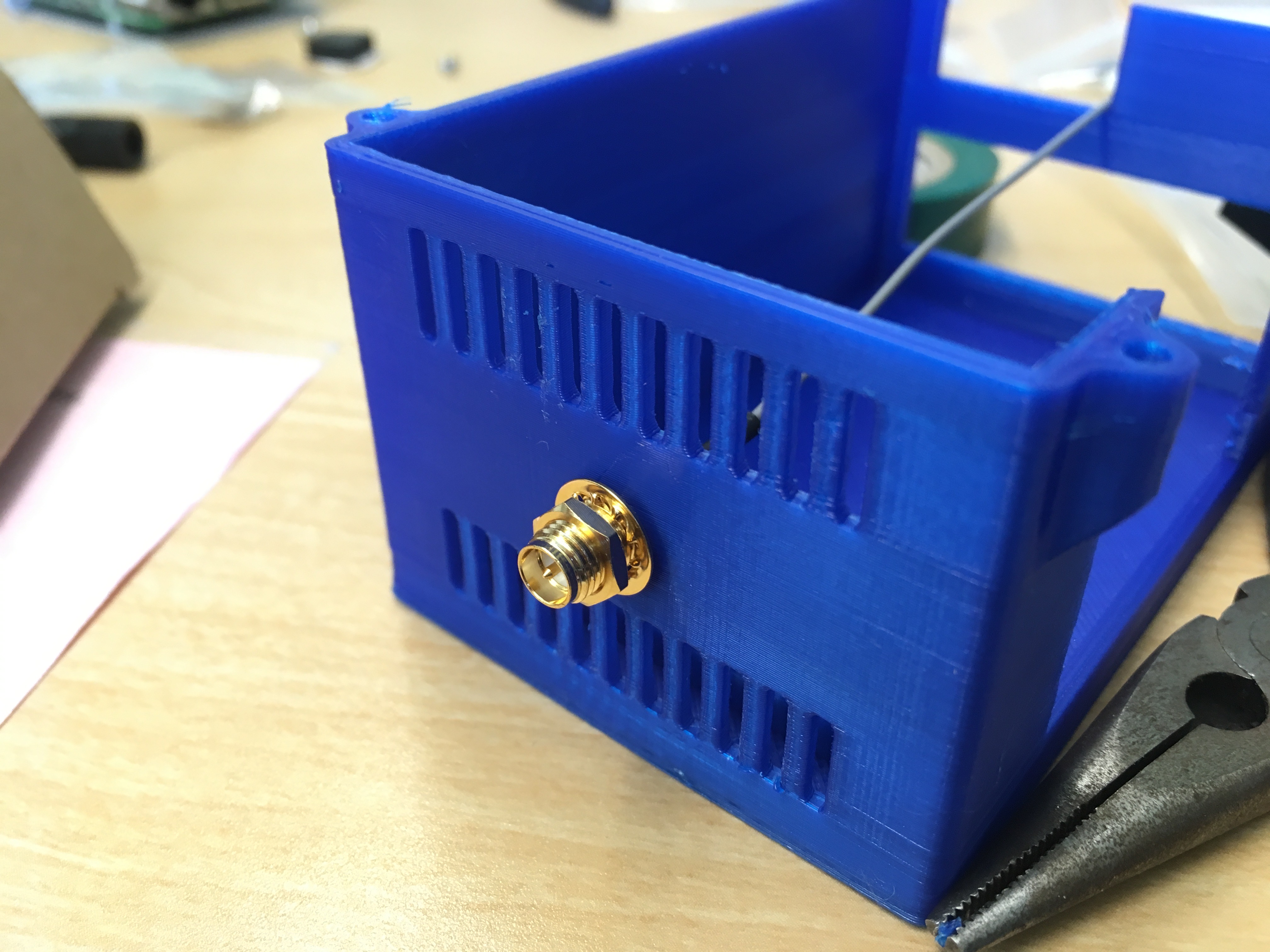
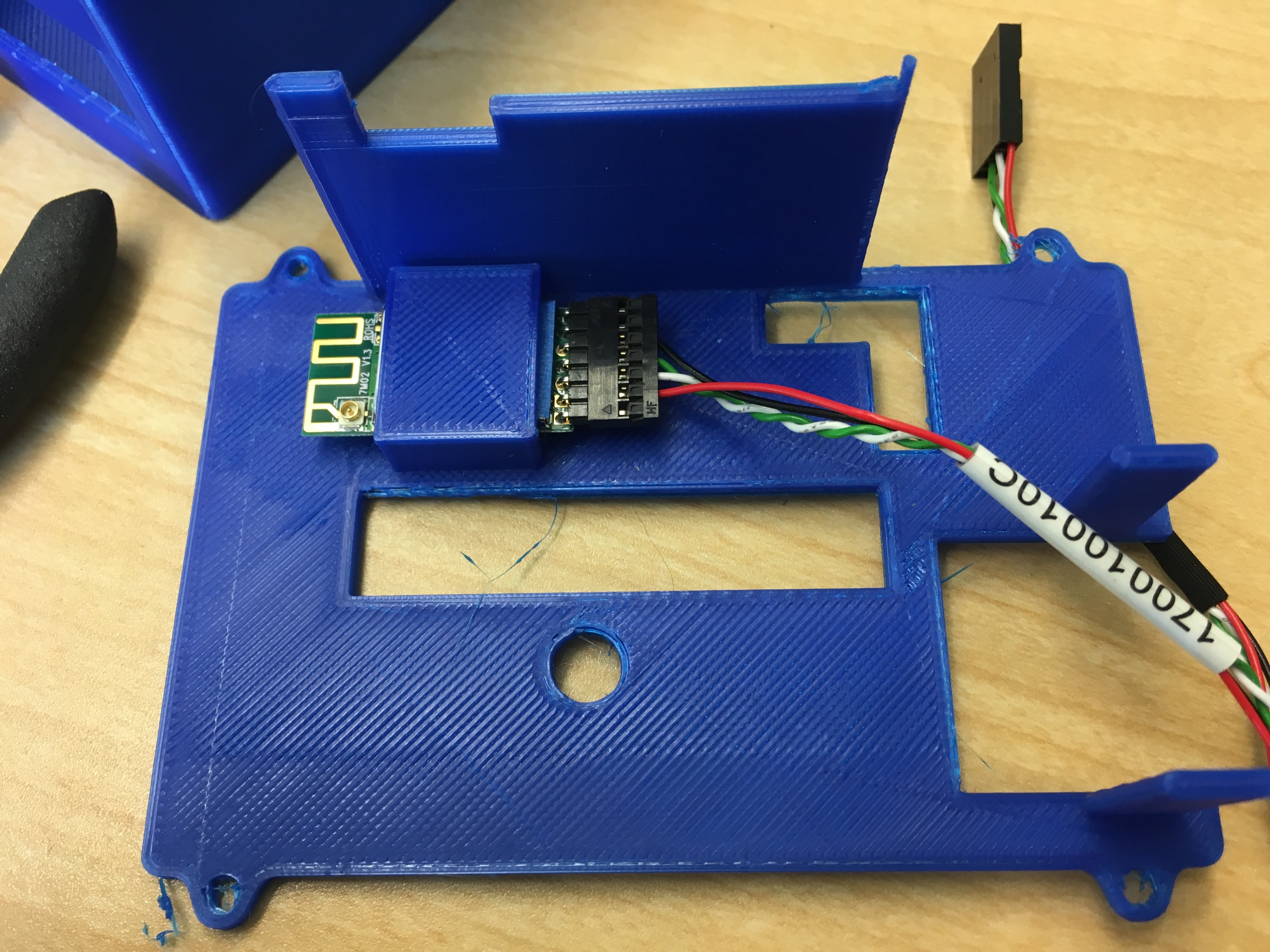
- Place the UP board in the bottom case and slide the WiFi card into the bracket on the top case
- Feed the antenna adapter through the hole on the back of the bottom case and attach with the lock washer and nut.
- slide the two pieces of the case together and secure with four M3x6 machine screws.
- Connect the GPS/Compass unit to the PXFMini using a JST GH cable
- Connect RC input processor to the PXFMini using a JST GH breakout cable
- Connect the telemetry radio to the UP Board with a micro-USB cable
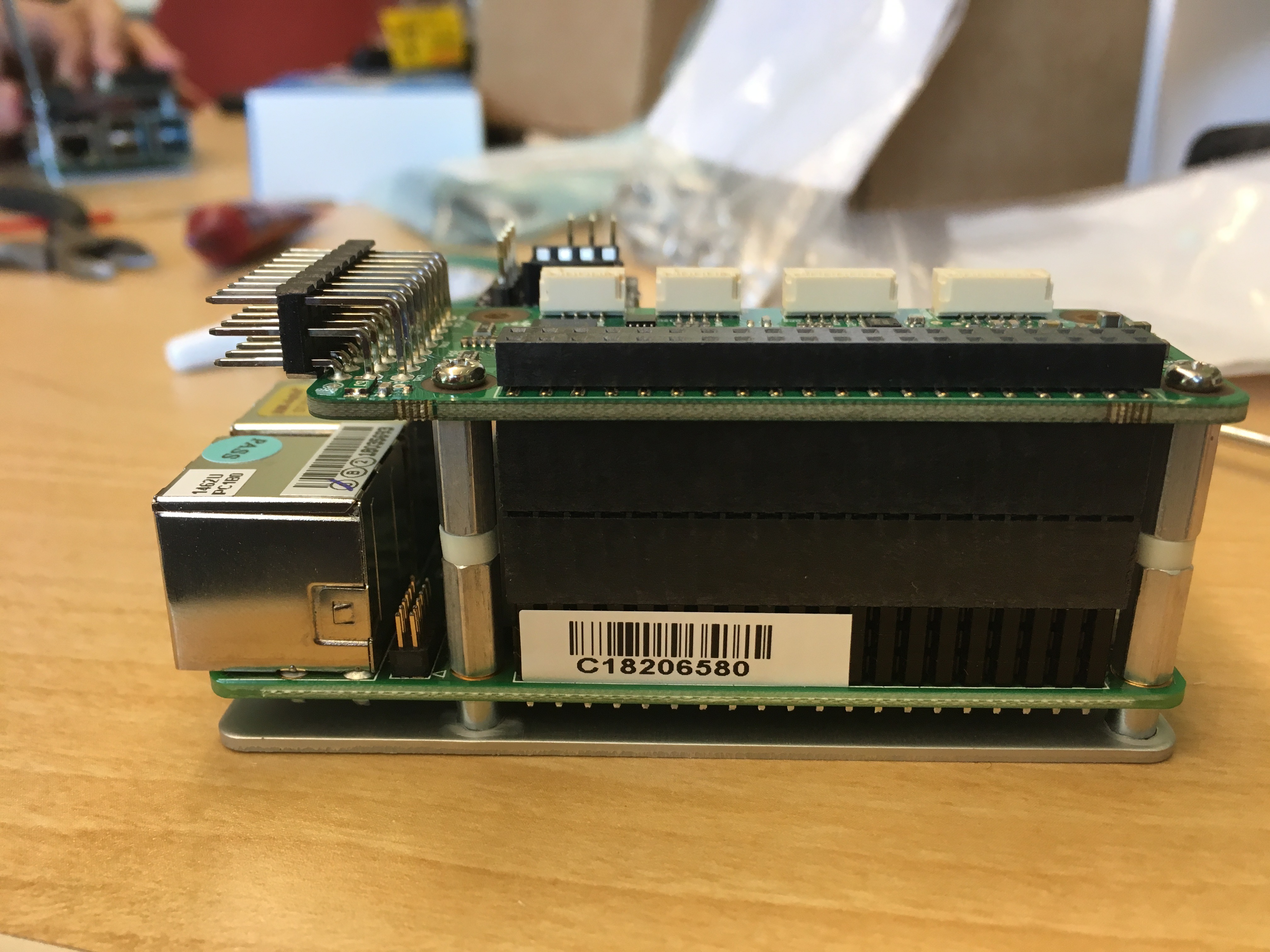
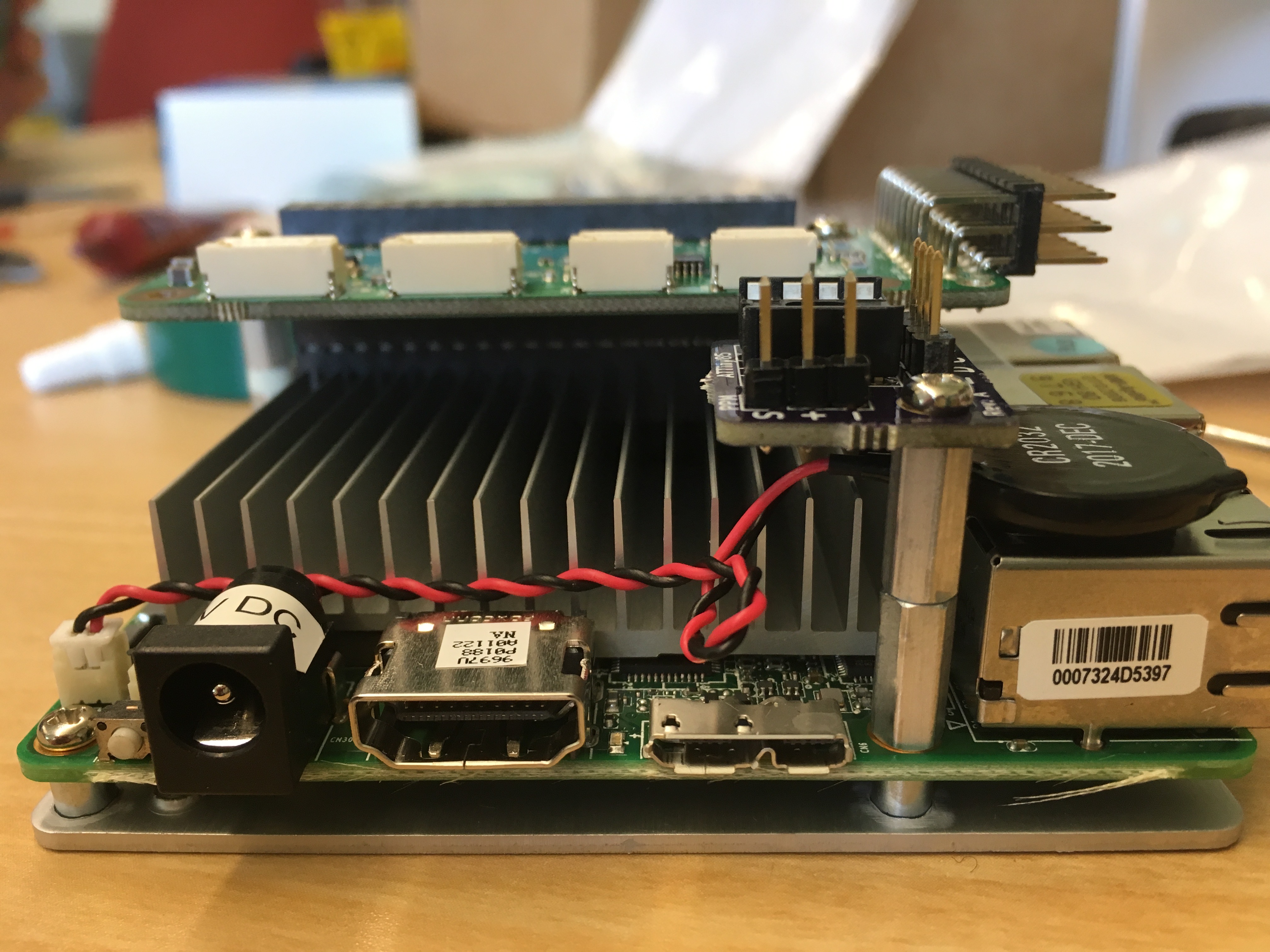
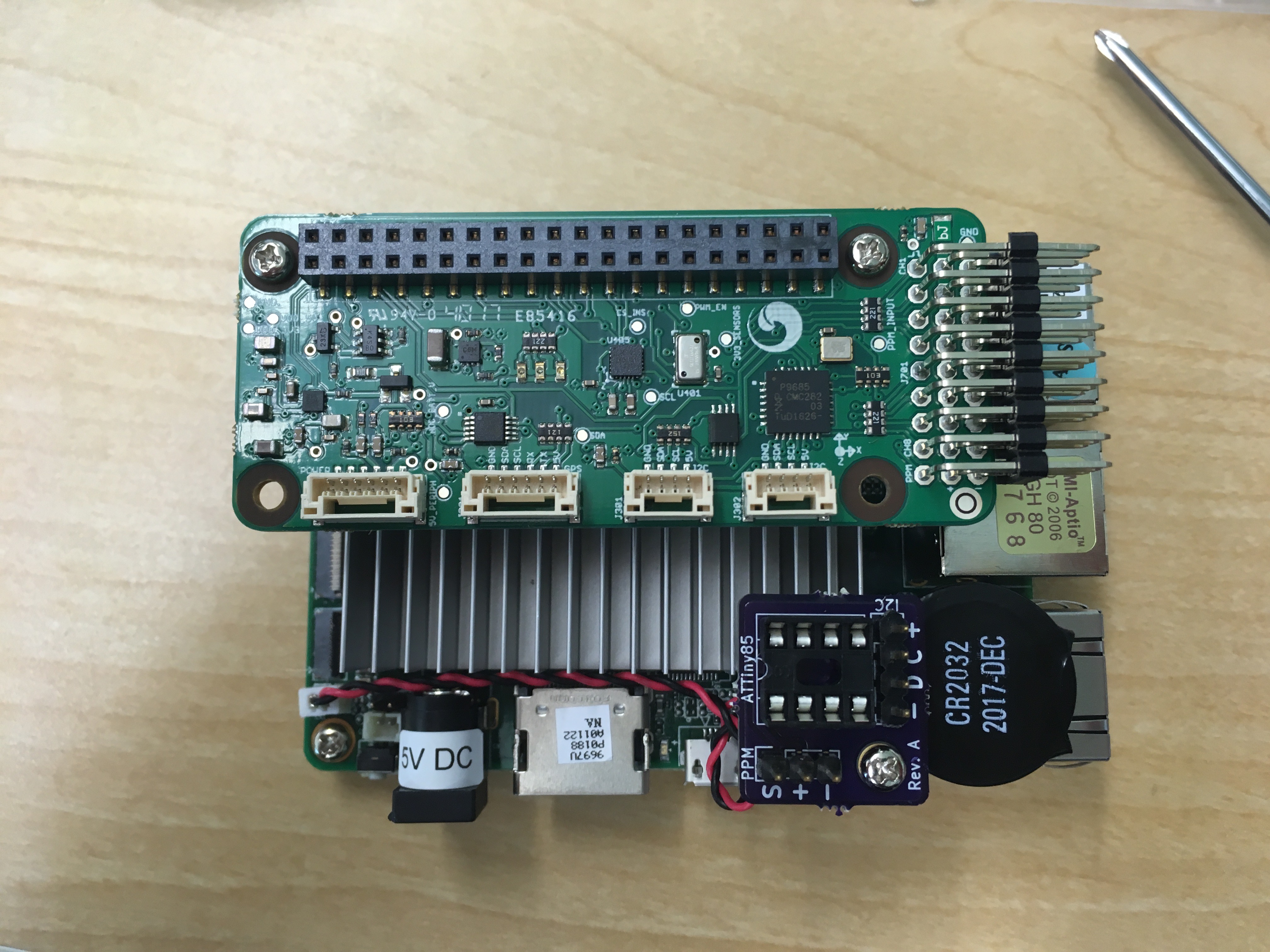
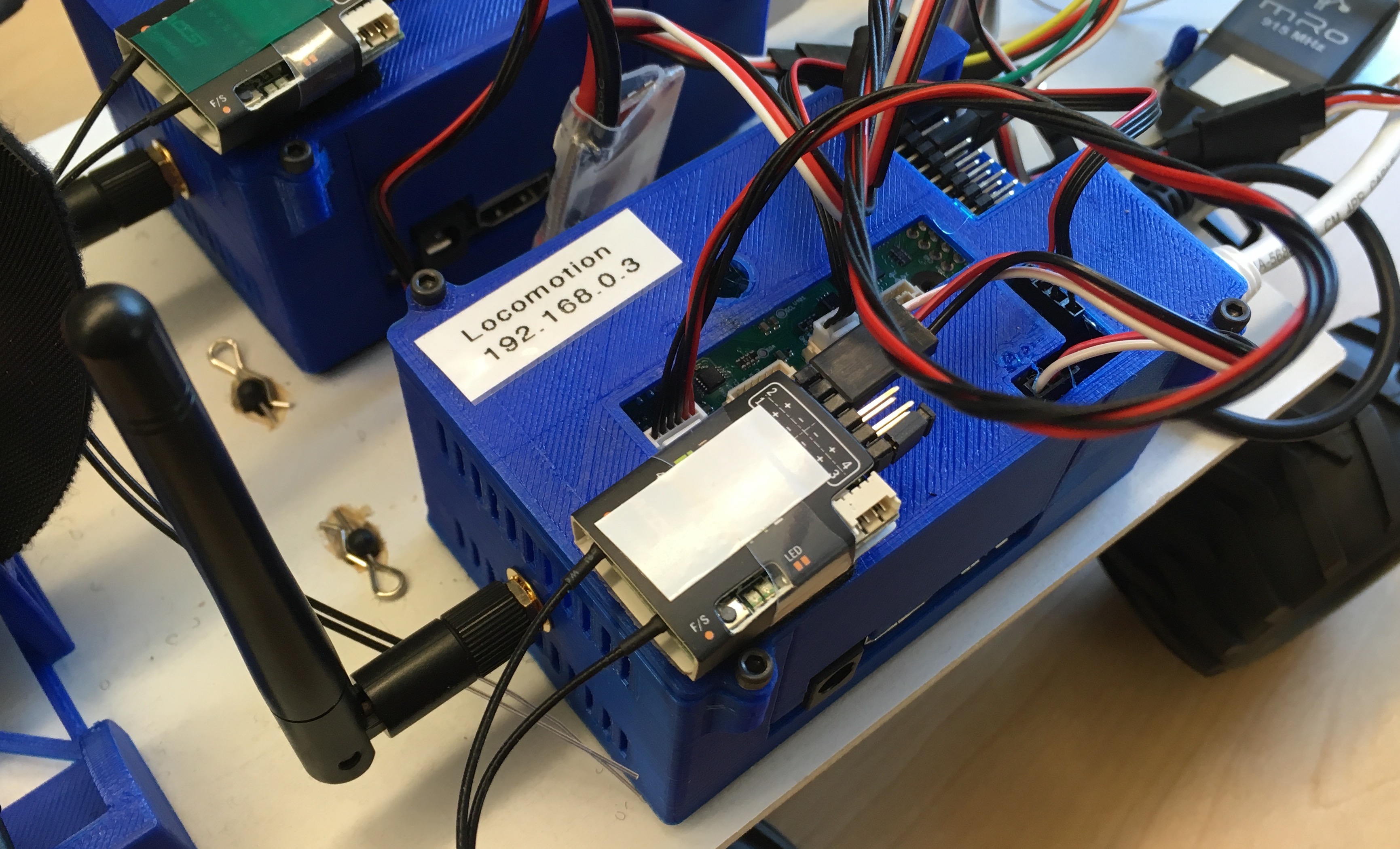
The final construction of the the UP Board-based autopilot will look similar to this:
Build OS Image
The next step is to build a custom operating system image using the Yocto Project build system, Poky.-
Download
pokyand cd into the directory:git clone -b krogoth-15.0.3 git://git.yoctoproject.org/poky.git
cd poky -
Download the OpenEmbedded meta layer:
git clone -b krogoth https://github.com/openembedded/meta-openembedded
-
Download the Intel BSP layer:
git clone -b krogoth git://git.yoctoproject.org/meta-intel.git
-
Download the Intel UP board BSP layer:
git clone -b krogoth https://github.com/emutex/meta-up-board
-
Download the Java meta layer:
git clone -b krogoth git://git.yoctoproject.org/meta-java.git
-
Download the Virtualization meta layer:
git clone -b krogoth git://git.yoctoproject.org/meta-virtualization.git
-
Download the START-Rover meta layer:
git clone git://gitlab.eecs.umich.edu/wrg-code/meta-start-rover.git
-
Create the build environment (this will change into the
builddirectory):TEMPLATECONF=meta-start-rover/conf source oe-init-build-env
-
Build the OS image. There is a trusted image and a locomotion image.
Both rovers are configured with static IPs: trusted is
192.168.0.2and locomotion is192.168.0.3.bitbake meta-start-rover-trusted bitbake meta-start-rover-locomotion
-
Write the generated iso
(
tmp/deploy/images/up-board/meta-start-rover*.iso) to a flash drive.
Configure Software on UP Board
- Attach USB drive created in the previous section to the UP Board and boot
- Press esc at boot to enter system setup
-
Ensure that
Advanced > HAP Configurationhas the following settings:LPSS I2C #1 Support [ACPI Mode] I2C #1 Speed [400KHz] LPSS I2C #2 Support [ACPI Mode] I2C #2 Speed [400KHz] LPSS PWM #1 Support [ACPI Mode] LPSS PWM #2 Support [ACPI Mode] LPSS SPISupport [ACPI Mode] LPSS HSUART #1 Suppor [ACPI Mode] SCC SDIO Support [ACPI Mode] I2CO/GPIO Selection [GPIO] I2S/GPI Selection [GPIO]Save and exit configuration - Press F7 to bring up the boot device menu. Select the USB drive from the menu, and follow the prompts to install the OS. Allow installation to complete and reboot.
-
DNS is currently misconfigured. Add a nameserver to the
resolv.conffile.echo "nameserver 192.168.0.1" > /etc/resolv.conf
-
Download and build Ardupilot:
cd ~
git clone -b upboard-update https://bitbucket.org/kevinaangstadt/ardupilot
cd ardupilot
git submodule update --init
./waf configure --board=upboard
./waf build
-
Binaries for Ardupilot are available in
build/up-board/bin
Running Ardupilot
Ardupilot binaries require several flags to configure external devices:
-
-Athe console output (this generally spits out garbage) -
-Bthe primary GPS (located at/dev/ttyS1on the UP Board) -
-Cthe primary telemetry radio (located at/dev/ttyUSB0on the UP Board)
Execution of ardupilot might then look something like the following:
~/ardupilot/build/up-board/ardurover -A /dev/null -B /dev/ttyS1 -C /dev/ttyUSB0
Last modified: 2018-07-06