MOBILE communication devices have become quite common in today’s world. With the increasing need to effectively utilize bandwidth, and have efficient and compact devices, the linearization of power amplifiers has become an important issue. In order to operate with high efficiency, power amplifiers are driven near and into compression, which results in high levels of distortion. This distortion, both AM-AM and AM-PM, manifests itself in the form of spectral re-growth, causing unwanted power leakage into other channels. Adjacent channel power ratio (ACPR) is a common figure of merit to quantify the spectral re-growth. For acceptable ACPR, power amplifiers must be operated at a power back-off. This results in lower efficiency.
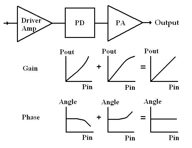
Several techniques have already been developed to linearize power amplifiers. Among these are feedback, feed-forward and predistortion. Because of their relative simplicity, compactness and modularity, predistorters (PDs) are of particular interest. A PD produces a transfer function that is the opposite of the PA’s transfer function. This results in a more linear output and lower distortion at higher power, thus the ability to operate with higher efficiency.
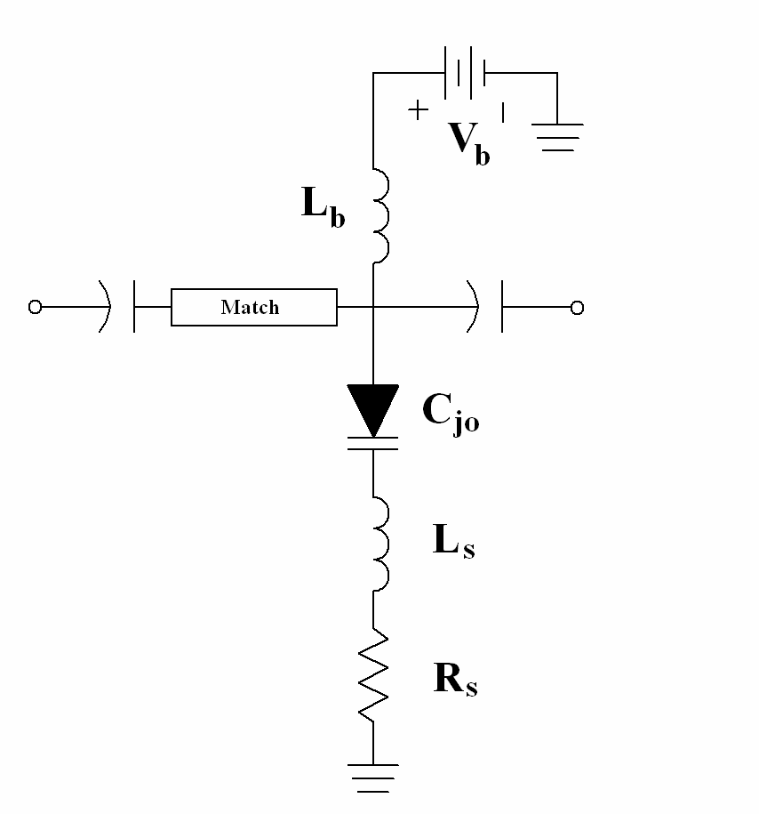
The PD is comprised of a bias network, the PD core and a quarter-wave input match. The two end capacitors are used for DC blocking. The core of the circuit is a series resonator in shunt, with a reverse biased varactor diode serving as a tunable capacitor.
The power transfer function of the PD is intimately tied to the frequency response of the resonant tank. At low power, the capacitance of the diode remains nearly constant, as dictated by the applied bias. As the RF power increases, the effective capacitance of the varactor diode also increases. This causes a shift in the phase and amplitude transfer functions. It is also possible to accomplish negative phase deviation by operating off the resonant frequency, which retains the PD circuit’s flexibility.
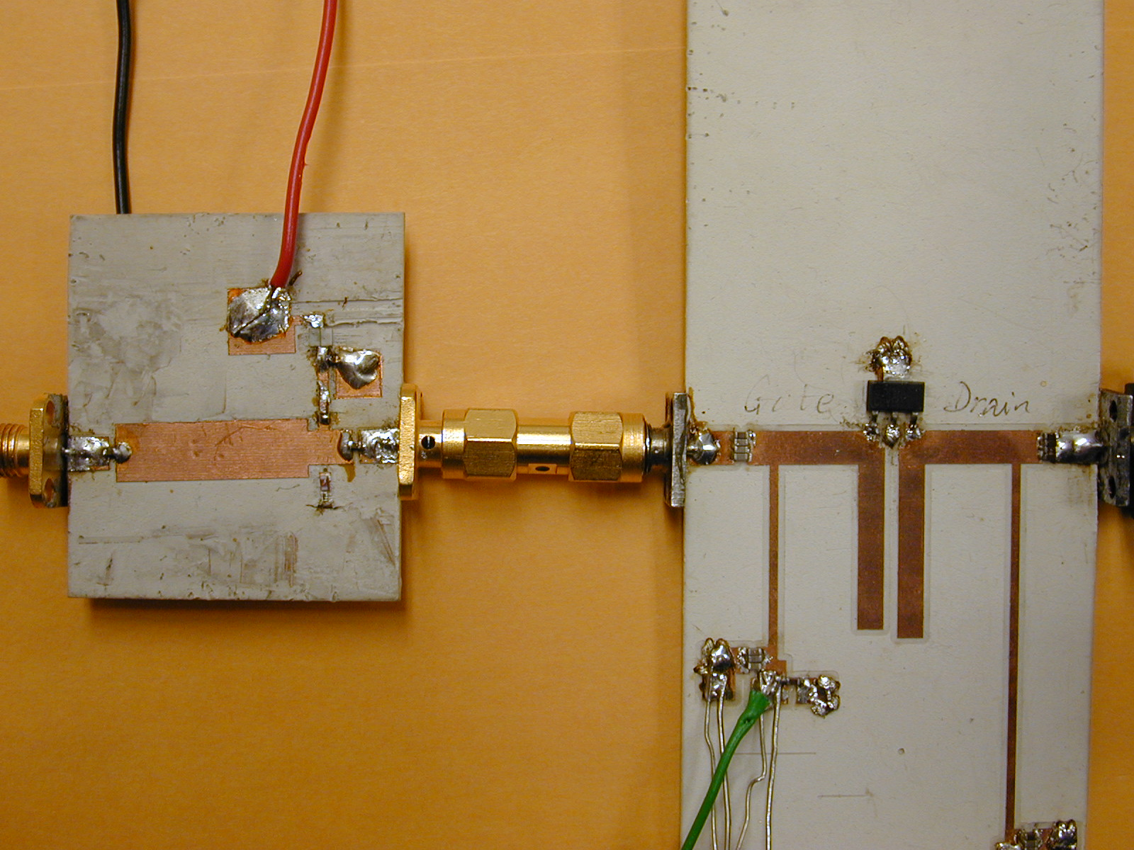
A PD was designed and fabricated for positive phase deviation to compensate for phase compression of the PA used. The PA was designed for operation at 1.8 GHz with 9 dB gain and 21 dBm output power.
The PD was biased at different points to demonstrate the control over the linearized PA’s transfer function and ACPR improvement. All power transfer functions were measured at 1.8 GHz. A standard NADC test signal at a carrier frequency of 1.8 GHz was used for distortion measurements, and ACPR was taken at 12.5 kHz bandwidth with 30 kHz offset. At a -2.6 V bias, the 1-dB compression point was improved from 21 dBm to 22.8 dBm with an insertion loss of 1.4 dB. The improvement in ACPR reaches a maximum of 11 dB at 17.5 dBm out for the PD biased at -3.0 V.
[1] N. Gupta, A. Tombak, and A. Mortazawi “A predistortion linearizer using a tunable resonator,” IEEE MTT-S Int. Symp. Dig., vol. 2, pp. 6-11, June 2004.
[2] N. Gupta, A. Tombak, and A. Mortazawi “A predistortion linearizer using a tunable resonator,” IEEE Microw. Wireless Comp. Lett., vol. 14, no. 9, pp. 431-433, Sep. 2004.


