The assignment is due on Saturday, Dec. 12th,
2015 at 12 noon.
Overview
In this assignment you will extend the view3D from PA2 to
render animated textured scenes.
The given support code parses an input X3D file, partially constructs
a scene graph, inserting various X3D nodes into it, and then passes
the scene to OpenGL for rendering. The X3D file format is described in
the
X3D Specification. Most tasks require modifying the
scene.cpp file (as usual, look for ``YOUR CODE
HERE''). As part of your assignment you will need to create an
example X3D scene file that will show an animated humanoid
character moving through a scene.
Tasks
The first three tasks of this assignment familiarize you with
how texturing fits into a scene graph. The first
two tasks should be easy peasy for you by now. The third one introduces
you to texture transform.
When you build the provided code as is, you will likely get warnings about
the index variable being not used in various functions in scene.cpp.
You can ignore these warnings for now. The index variable will
be used by your code. As is, view3D will display scenes/aclock.x3d
as shown on the right.
1. Texture Setup. The provided view3D application
can load texture image
from a JPEG or PNG file and store it as an object of Image
class (image_ points to the image). To
enable texturing, you need to generate a new OpenGL texture handle
(ID) and set up OpenGL for texturing. Modify
the SetupTexture method of
the X3ImageTexture
class. You MUST enable mipmapping to avoid aliasing effects.
Now scenes/aclock.x3d
should look like on the right. Also check that
fish-textured.x3d shows the fins striped.
Image files used for texturing MUST be in the same
folder as your scene file. 5 points
2. Textured Cylinder. When rendering geometry, you need to
specify texture coordinates for each vertex. Modify the
X3Cylinder::Render() method to render a textured cylinder.
Texture coordinates MUST be assigned as specified in the X3Cylinder spec. You may want to consult
the XBox::Render() and XCone::Render()
methods for examples. Now scenes/aclock.x3d should look
like on the right (notice the upside down clock face). You should also be
able to view scenes/cylhead.x3d now. 10
points
3. Texture Transforms. OpenGL can apply tranformations to
specified texture coordinates before using them. Modify
the X3TextureTransform::Render() method to enable
texture coordinates transformations. You MUST implement it as
described in
the X3TextureTransform
spec. This is similar to what happened in
the X3Transform
node; however, there is no hierarchy and no need to use the matrix
stack. Just override the transforms every
time X3TextureTransform is needed. Now scenes/aclock.x3d
should look like on the right (notice the corrected clock
face). Also check that scenes/wall.x3d shows the correct
mountain panorama. 10 points
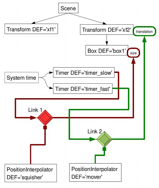
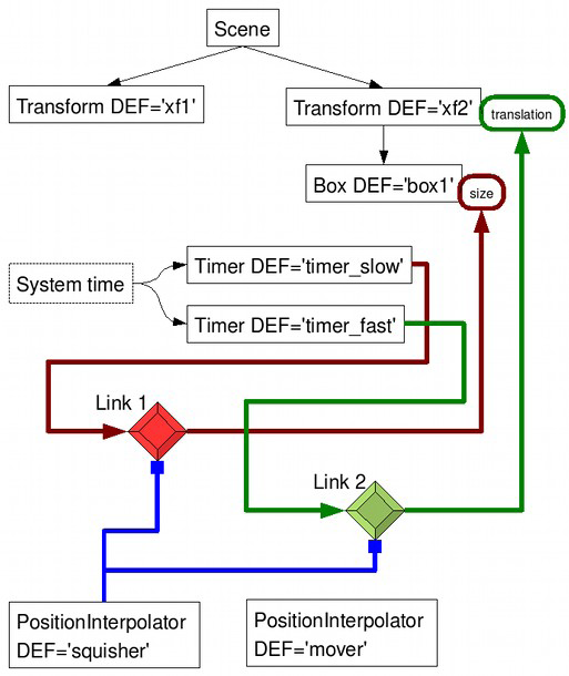
4. Linear interpolation. The provided support code has
some basic animation capability in
the Timer, Interpolator,
and Link nodes. Each Link specifies
which Timer's time to feed into which
Interpolator, to update which field of which node
(see the section on Field Update
Mechanism below).
Study the provided code that implements piecewise linear
interpolation for
the X3ScalarInterpolator
and
the X3PositionInterpolator
classes. Given an array of keys, a corresponding array of
values, and a time value, the code calls
the X3InterpolatorNode::FindKeyInterval() method to
determine the index between which two keys the time falls. The
code computes an in-between time distance between the two keys
and returns a linear interpolation of the values associated with
the two keys. Due to polymorphism, the code
for X3ScalarInterpolator::LinearInerpolation()
and X3PositionInterpolator::LinearInerpolation()
are identical. For rotations, angles and axes must be
interpolated separately. Implement linear interpolation for
X3OrientationInterpolator
that linearly interpolates the axes and angles separately and
returns the two together as a rotation_t.
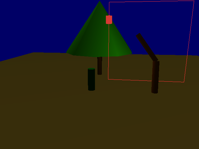
View scenes/spline-linear.x3d. Hit SPACEBAR to start
the animation. All four objects in the scene should animate,
each using a separate Interpolator. Study the
file scenes/spline-linear.x3d to see which object uses
which Interpolator. The scene scenes/aclock.x3d
also animates. This task is mainly about getting you to spend
the time to read the spec on Field Update Mechanism and
to study the codes that implement linear interpolation and to
study the scene file so that you're familiar with the support
code structure for animation. Make sure you're thoroughly familiar
with the spec and code and scene file before you move on to the
next two tasks. 5 points
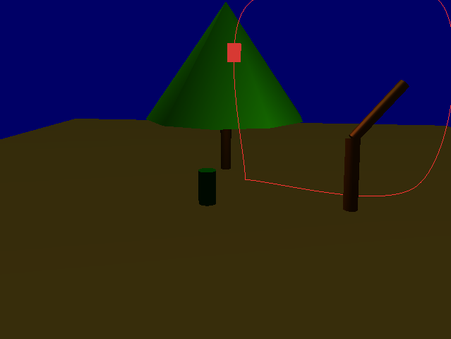
5. Spline Interpolation. Implement spline interpolation
for the X3ScalarInterpolator and X3PositionInterpolator
classes to enable animated content rendering--with smoothly
varying parameters, as well as to enable rendering of
smooth X3Curve. Use the Catmull-Rom splines (with tension zero) to
produce smooth interpolation. You only need to implement smooth
interpolation for the scalar and position values, not
rotations (which would require use of quaternions). For easier debugging,
use the X3Curve node to draw a curve in space (X3Curve
is not part of standard X3D). The X3Curve has an
X3PositionInterpolator as a child. It draws a curve in
space that samples the X3PositionInterpolator's trajectory.
Once you have these implemented, you should
be able to view all objects in the scene scenes/spline-smooth.x3d
animated as in the previous task, but smoother. 15 points
6. Humanoid Walking. Create an X3D scene file that
renders an animated humanoid walking through some scene. For
full credit, the character should be textured, have two legs
(comprised of upper legs, lower legs, and feet), two arms, a
body, a head, and exhibit a proper walk cycle. The walking
should propagate the character through the scene at the
appropriate rate without sliding. It is acceptable to use
cylinders and boxes for rendering the character. This is 55% of
the assignment; be sure to treat it as such!
The animated humanoid must be modeled as an articulated
hierarchical character model. You must tie together
several Interpolation nodes with proper rotation
transformations of the skeletal links to produce a walking
figure. Once a basic periodic walk cycle is
created, you can propagate it through a scene with a translation
transform. (As an optional extension, i.e., not required, walk
your character on a curved path, which would mean changing its
orientation also). Texture your character with some images to
help indicate that you have control over your scene viewer
(i.e., the head should point forward and knees bend backward).
Do not worry about being overly realistic; think of your
character as a puppet/robot (though the character parts should
not fly off in different directions during animation). You MUST
name your scene file walk.x3d. On the right is an
example. Be creative and don't create a scene similar to this
one! The best way to figure out enough X3D syntax to complete this
task is to study spline-smooth.x3d. Some students have
also found this optional
X3D
tutorial useful (if you do consult it, try not to spend too
much time on it!). 55 points
The program view3D should be called with one
command-line argument--the name of an X3D scene file. We have
included a few in the scenes sub folder.
The code needs to be linked against the png, jpeg,
expat and the usual OpenGL, GLU, and GLUT libraries; and its
compilation requires the corresponding header files. For instructions
on how to install these libraries, please see the
course note.
Your code must not require other external libraries or include files
other than the ones included in the support code or listed in this
spec (e.g., do not include xmat.h, you don't need it).
The following keyboard shortcuts are defined
for view3D (you may bind other operations to keys
in view3D.cpp:kbd(), but do not change these
predefined keys):
'q' or ESC: quits the program
SPACE: pauses/resumes animation
RIGHT_ARROW: moves one frame forward (when the animation is
paused)
LEFT_ARROW: moves one frame back (when the animation is paused)
HOME: moves to time zero (when the animation is paused)
You can rotate the object around by left-click-and-hold while dragging
the mouse about. Dollying in and out can be done by
right-click-and-hold while dragging the mouse about.
Submission Guidelines
As with PA1, to incorporate publicly available code in your
solution is considered cheating in this course. To
pass off the implementation of an algorithm as that of another is also
considered cheating. For example, if the assignment asks you
to implement sort using heap sort and you turn in a working program
that uses insertion sort in place of the heap sort, it will be
considered cheating. If you can not implement a required algorithm,
you must inform the teaching staff when turning in your
assignment, e.g., by documenting it in your writeup.
Test the compilation!
Code that does not compile
will be heavily penalized.
The creative portion of this project, Task 6, will take some time to
do right if you are interested in getting a good grade. It involves a
fair amount of trial and error.
Your platform: Linux, Mac OS X, Windows, or any other.
Anything noteworty about your implementation, e.g., if you implemented
quaternions.
Feedback on the assignment.
Name the file writeup-uniqname.txt.
For example, the person with uniqname
tarukmakto would create
writeup-tarukmakto.txt.
Your "PA4 files" then consists only of
your writeup-uniqname.txt,
scene.cpp, your humanoid walking scene file from Task 6
(which MUST be named walk.x3d), and new texture file(s)
you use as part of Task 6.
To turn in your PA4, upload a zipped or gzipped tarball of your
PA4 files to the CTools Drop Box.
Keep your own backup copy!
The timestamp on your uploaded file will be your time of submission.
If this is past the deadline, your submission will be considered late.
You are allowed multiple "submissions" without late-policy implications
as long as you respect the deadline.
Turn in ONLY the files you have modified.
Do not turn in support code we provided that you haven't modified.
Do not turn in any binary files (object, executable,
dll, library, or image files) with your assignment. Your
code must not require other external libraries and include files
other than the ones listed in the Makefile.
Do remove all printf()'s or
cout's and cerr's you've added for debugging
purposes.
General Information
The
General Information section from PA1 applies. Please review it if
you haven't read it or would like to refresh your memory.