
Copyright © 2010-2011,
Thomas Schmid,
Matt Smith,
Ye-Sheng Kuo,
Lohit Yerva,
and Prabal Dutta.
Compile and install a simple LED blinking application using the ARM Cortex-M3.
In Lab 1 you learned how to program the FPGA side of the Actel SmartFusion. For Lab 2, we will use the integrated ARM Cortex-M3. Because of the extreme flexibility and interconnect potential of the SmartFusion, we will first have to program the FPGA with some wiring. This will allow the Cortex-M3 to access the external GPIO lines connected to the LEDs. For now, download the following Libero Project Lab 2 FPGA Wiring. You will learn more about this project in Lab 3. For now, just program the FPGA with it as you learned in Lab 1.
You will have to synthesise, place and route, and program the FPGA with this project. Here is a quick reminder of the steps you have to perform.
 or choose
SmartDesign->Generate Design... from the menu. A dialog should
appear informing you that the generation was successful. Click
OK.
or choose
SmartDesign->Generate Design... from the menu. A dialog should
appear informing you that the generation was successful. Click
OK.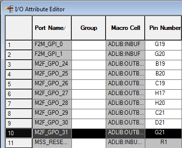
 on the top left, and close the I/O Attribute Editor.
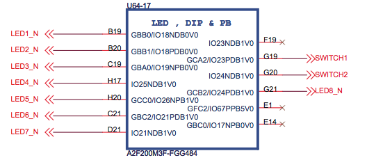
The signal and pin-out configuration is as follows:
First, close any open window. We won't need Actel Libero anymore for the rest of this tutorial, as the Cortex-M3 is programmed using a different toolchain.
Next, we need to create an empty directory that will hold our programming
code. Open the command line by clicking on START and type
cmd.exe into the search field. Click on the application that gets
found (in Windows 7 it is a black symbol with a C:\_ inside of
it). The command line should be open now and by default, you should be in your
home directory. Create a new directory by typing (or copy/pasting)
mkdir lab2and hit the
Enter key. To change into the directory, execute
cd lab2Next, we have to setup the environment and let it know where the compiler, linker, and debugger can be found. We accomplish this by adding the Code Sourcery to the PATH environment variable. Type the following into your console
set PATH=c:\Actel\Libero_v9.1\SoftConsole\Sourcery-G++\bin\;%PATH%Verify that you typed in the right directory and that by executing the make application:
makeThe output should look something like this:
make: *** No targets specified and no makefile found. Stop.If instead you see a message informing you that
make is not a
recognized internal or external command, then verify that the path we typed in
above has the right spelling, and that it really contains the Code Sourcery
tools.
Now we create a simple assembler file with one global label "main" and a local label for a branch. Create a file "main.s" with the following content (Use start->All Programs->Notepad++):
	.equ  STACK_TOP, 0x20000800

	.section .int_vector,"a",%progbits @ First linker code section
	.global _start                     @ Linker entry point
_start:
	.word STACK_TOP                    @ Stack pointer
	.word main                         @ program counter start address
	@ End of int_vector section

	.text
	.syntax unified
	.type main, %function
main:
	b	main
	.end
Q: What does this application do?
We now have to compile the assembly file into an object file. We accomplish this by executing the GNU GCC compiler. The created object file will be called main.o, using the input file main.s to create it. Type the following command into the command line:
arm-none-eabi-gcc -mthumb -mcpu=cortex-m3 -O0 -Wall -c -nodefaultlibs -nostartfiles -o main.o main.sThis will execute the arm-none-eabi-gcc compiler. The arguments mean the following:
arm-none-eabi-gcc --help for a general help, or
arm-none-eabi-gcc --target-help for target specific command line
options. A complete list of GCC Command options can be found on the
GCC
Command Options website. There is also more documentation in the Code
Sourcery directory under share/doc/arm-none-eabi/.
If you want to see what the code looks like that gcc generated, you can disassemble it by using objdump as follows:
arm-none-eabi-objdump -S -D main.oThe output of this program is the disassembled object. Ignore the .ARM.attributes section. What is the second address and value under _start?
It is now time to link our object into the final binary. We currently have only one object, and thus the linking is trivial. However, in more sophisticated applications, the linker will pull together code from several different objects and libraries to produce one binary output file.
The linker needs an input file to let it know about the memory structure.
Create the following file named link.ld (you can type start
notepad link.ld):
OUTPUT_FORMAT("elf32-littlearm", "elf32-bigarm", "elf32-littlearm")
OUTPUT_ARCH(arm)
ENTRY(_start)

MEMORY
{
 /* SmartFusion internal eSRAM */
 ram (rwx) : ORIGIN = 0x20000000, LENGTH = 64k
}

SECTIONS
{
 .text : /* Within the .text section: */
 {
    *(.int_vector) /* Interrupt Vector Table is always first */
    *(.text*)      /* All other text sections follow */
 } >ram
}
end = .;
Next, we link the object file:
arm-none-eabi-gcc -mthumb -mcpu=cortex-m3 -specs=bare.specs -nodefaultlibs -nostartfiles -Tlink.ld -Wl,-Map=lab2.map -o lab2 main.oThis will invoke the linker (note we omitted the -c option to gcc). The new arguments mean the following:
arm-none-eabi/lib.lab2 fileYou now have a binary object file, lab2. Disassemble it using:
arm-none-eabi-objdump -S -D lab2
How is it different from the output of the main.o file? (value 20000009 should exist at address 20000004)
Why is <_start> before <main>?
We need to change the format of our binary file in order to program the Cortex-M3 with our application. Execute the following commands, one after another:
actel-map -o "memory-map.xml" lab2 arm-none-eabi-gcc -mthumb -mcpu=cortex-m3 -specs=bare.specs -nodefaultlibs -nostartfiles -Tlink.ld -Wl,-Map=.map

arm-none-eabi-objcopy -O ihex lab2  "lab2.hex"

arm-none-eabi-objcopy -O srec lab2 "lab2.srec"

arm-none-eabi-objdump -h -S lab2 > "lab2.lst"
Find out what these specific objcopy commands do by using an Internet search
and the command line arm-none-eabi-objecopy --help command.
We use the GNU Debugger (GDB) to upload our binary to the Cortex-M3. This particular flash application needs a helper application to lock the programmer. Therefore, we have to run an actel keep-alive mutex. Execute the command:
start actel-keepalive actel-keepaliveThis will open a new command window running the actel-keepalive application. Don't close this window, as long as you need GDB. You can, however, minimize it to the taskbar.
Switch back to your other command window and start GDB by typing
arm-none-eabi-gdbThen, execute the following commands. The lines proceeding with a "#" are comments and explaining what the command does:
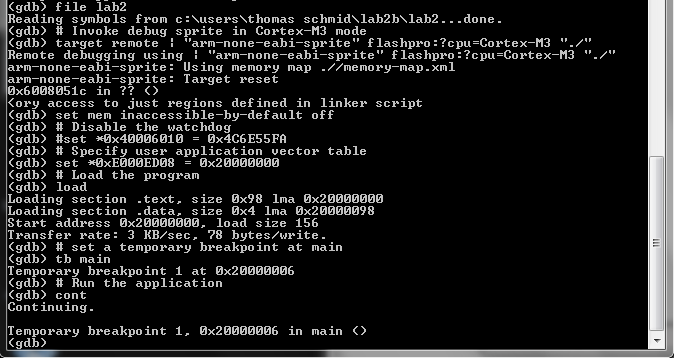
# Load the symbol table
file lab2
# Invoke debug sprite in Cortex-M3 mode
target remote | "arm-none-eabi-sprite" flashpro:?cpu=Cortex-M3 "./"
# Don't restrict memory access to just regions defined in linker script
set mem inaccessible-by-default off
# Disable the watchdog
set *0x40006010 = 0x4C6E55FA
# Specify user application vector table
set *0xE000ED08 = 0x20000000
# Load the program
load
# Run the application
cont
After the last line, the output of GDB should look like this:
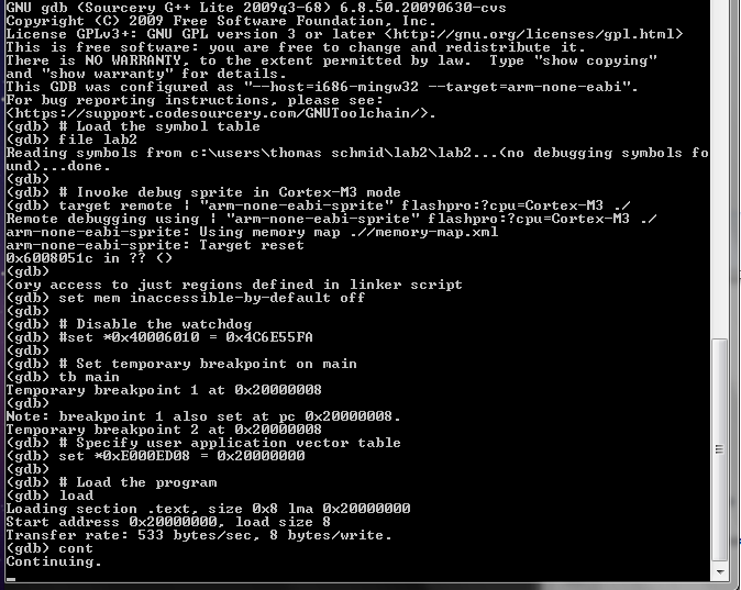
Congratulations! You just started your first application on the Cortex-M3. The yellow LED D14 should be blinking. Nevertheless, this application is not doing much as it is just busy looping forever.
It's now time to hit ctrl-c to stop the execution (or quit to exit GDB). You will again
be presented with the GDB prompt. This prompt allows you to examine the state
of your embedded platform and later on debug your code by looking at variable
values, memory, and registers. Go ahead, type help and explore
some of the capabilities of GDB. For example, type info
registers. However, note that we compiled our code without debugging
information. Thus, some of the commands won't show you any useful information.
Can you tell where in your application you stopped your application if you
type info registers? Explain how and why.
Now add the following two instructions between main: and b main lines.
mov r1, #1
add r1, r1, #1
Program the SmartFusion and examine the registers for their values. Did it work?
Now, write a for loop in assembler by using one of the registers as incrementing variable. Count up to 100 before you go into the busy loop. Use the following debugging setup to test and debug your code.
Please READ the following helpful hints


LSL{S} Rd, Rm, <Rs|sh>), <Rs|sh> can be a register or a constant.
You already know how to launch GDB. However, its usefulness in order to find
information about the running application were fairly limited so far. The
compiler has to annotate your binary with special information in order to let
GDB know more about the application. We accomplish this by passing the
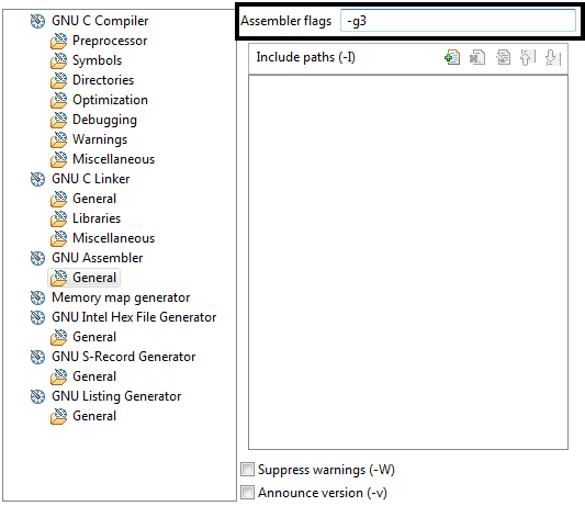
-g3 option to GCC.
Recompile your application but add -g3 to every non-linking call of GCC,
i.e., execute the following commands
arm-none-eabi-gcc -mthumb -mcpu=cortex-m3 -O0 -g3 -Wall -c -nodefaultlibs -nostartfiles -o main.o main.s

arm-none-eabi-gcc -mthumb -mcpu=cortex-m3 -specs=bare.specs -nodefaultlibs -nostartfiles -Tlink.ld -Wl,-Map=lab2.map -o lab2 main.o
Disassemble the lab2 binary now. Do you notice the difference to before?
Now, let's start GDB but this time, use the following script to run your application
# Load the symbol table
file lab2
# Invoke debug sprite in Cortex-M3 mode
target remote | "arm-none-eabi-sprite" flashpro:?cpu=Cortex-M3 "./"
# Don't restrict memory access to just regions defined in linker script
set mem inaccessible-by-default off
# Disable the watchdog
set *0x40006010 = 0x4C6E55FA
# Specify user application vector table
set *0xE000ED08 = 0x20000000
# Load the program
load
# set a temporary breakpoint at main
tb main
# Run the application
cont
Note that this time, we set a temporary breakpoint. Once you hit enter after
cont GDB will stop once it reaches the main function. Your GDB
shell should look something like this:
You are now ready to debug your application. The following list are some useful GDB commands. But they are by far not all of them. Use the GDB help for many more commands to inspect memory, backtrace code, or for different types of stepping or continuing executing the code.
| cont | continue execution until the next breakpoint |
| step | advance to the next line of code |
| step n | advance n code lines |
| next | step forward proceeding through subroutine calls |
| b main.s:10 | set a breakpoint on line 10 in the main.s file |
| list | show the source code around the current position |
| disp varname | display the content of variable varname every time we stop |
| bt | backtrace the function call history |
Try out to set a breakpoint in your loop. Then, check whether the register
increments correctly each loop.
Also, try to find out what the difference between b and
bt breakpoints is.
There are many many more commands in GDB. I encourage you to learn how to use
GDB, as it is THE tool for debugging your embedded system. For example, you
can put a watch on a variable, and interrupt the program code if the
variable, or memory location for that matter, changes. Also note that hitting
enter on an empty line in GDB repeats the last command. This is
extremely useful if you just want to step through code and advance one line at
a time.
Q: Can you tell in the debugger if you are still counting, or already in the busy loop? How? Write your new main code in the Answersheet.
Q: Explain the difference between the GDB commands step and
stepi. Use the GDB help command to find the
difference. Is there any difference with assembly source code? C code?
We now change our application to toggle the I/O lines connected to the LEDs. We accomplish this by using one of the peripherals of the Cortex-M3, the "General Purpose I/O Block (GPIO)". You can find more about this particular peripheral in the "Actel SmartFusion MSS User's Guide".
You will also learn more about how we really communicate with peripherals in later lectures and labs. For now, just read the following brief overview.
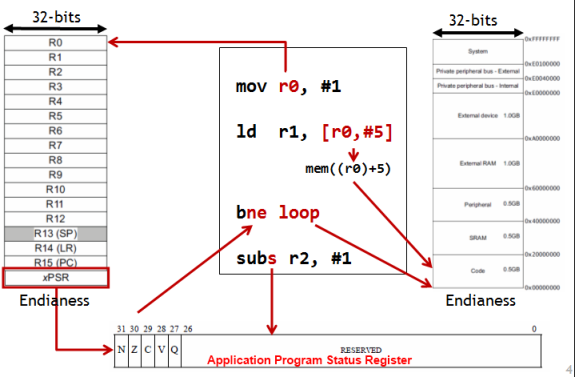
Remember the EECS 370 five stage pipeline? The only thing it could do was read and write from memory. In EECS 270, you built a D-Flip-Flop from gates and understood how to read and write from it. A DFF is also called register, which is physically the same at the registers in the processor. In the EECS 270 lab, you connected an LED to the output of a DFF or register. How does a processor control an LED? By writing values to the LED register. We use a method called Memory Mapped I/O to allow the processor to access the LED register. Basically, some region of the memory address space is allocated for the external I/O devices. The value that the processor thinks is sending to some location in standard memory is physically redirected to a new processor.
In the PostLab, you will be asked to write assembly functions that initialize and set the GPIO (use the completed main.s, which is provided after gpio.s, as a guide):
initGPIO task - In the case of the GPIO peripheral, we have two specific memory locations of interest. The first one is the configuration register. Note that these are not like the Cortex-M3 registers r0-r15. We just use the name register to indicate a specific location in memory. The microcontroller subsystem has 32 I/O lines, and each line has its own configuration register. The memory location starts at 0x40013000 for I/O line 0 (GPIO0). Each register is 32 bit long, and since the memory is byte indexed, we increment this memory location by 4 to find the configuration register for the other I/O lines, i.e., the configuration register for GPIO i is at (0x40013000 + i*4).
The bits in the configuration register have a specific meaning. The following table is a summary of the different configuration possibilities. To see further description, look at the "Actel SmartFusion MSS User's Guide, Revision 1" on page 317.
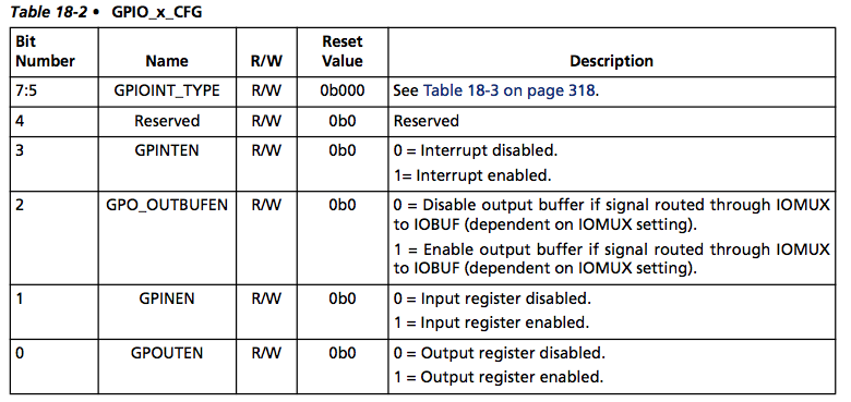
As we want our I/O lines to be output, we will have to write 0x1 into the configuration registers.
setGPIO task - Once we configured all the I/O lines we need, we can set their status with the output register GPIO_OUT located at 0x40013088. Every bit inside this register represents one I/O line. Thus, clearing bit i to 0, will pull GPIO i low, while setting bit i to 1, will pull GPIO i high.
For now, we are going to provide you with assembly function stubs. That is they are fully callable, but do nothing. In the following section we will use these functions stubs to illustrate a powerful software development tool. The assembly function stubs follow. For now just create gpio.s file with the following code in a new folder, lab2b.
	.equ GPIO_OUT_BASE, 0x40013000
	.equ GPIO_OUT, 0x40013088

	.text
	.syntax	unified
	.thumb

@ Configure the GPIOx to output
@ Inputs: GPIO number is provided in r0
@ Output:
	.global	initGPIO
	.type	initGPIO, %function
initGPIO:
	@ Load GPIO_OUT_BASE address

	@ Calculate the GPIOx register address
				@ left shift by 2 => i*4
				@ GPIO_OUT_BASE + i*4

	@ Write 1 to config register to set GPIO as output

	bx	lr @ Return

@ Set the value of all 32 GPIO output bits based on the input bits
@ Inputs: 32bit value is provided in r0
@ Output:
	.global	setGPIO
	.type	setGPIO, %function
setGPIO:
	@ Load GPIO_OUT register address

	@ Write 32bit value to GPIO output register

	bx	lr @ Return
Create the binary object by compiling the gpio.s file using
arm-none-eabi-gcc -mthumb -mcpu=cortex-m3 -O0 -Wall -c -nodefaultlibs -nostartfiles -o gpio.o gpio.s
Note the calls to initGPIO and setGPIO in the following code.
Create a new file called main.s with the following content:
	.equ	STACK_TOP, 0x20000800
	.equ	SYSREG_SOFT_RST_CR, 0xE0042030

	.section .int_vector,"a",%progbits @ First linker code section
	.global	 _start                    @ Linker entry point
_start:
	.word	STACK_TOP, main
	@ End of int_vector section

	@ Standard text section
	.text
	.syntax	unified
	.thumb

	.type	main, %function
main:
	@ Load SYSREG_SOFT_RST_CR address
	movw	r0, #:lower16:SYSREG_SOFT_RST_CR
	movt	r0, #:upper16:SYSREG_SOFT_RST_CR
	@ Reset GPIO hardware
	ldr	r1, [r0, #0]
	orr	r1, #0x4000
	str	r1, [r0, #0]
	@ Take GPIO hardware out of reset
	ldr	r1, [r0, #0]
	mvn	r2, #0x4000 @ move bitwise negation of 0x4000 into r2
	and	r1, r2
	str	r1, [r0, #0]

	mov	r0, #24
	bl	initGPIO @ Call initGPIO in gpio.s to initalize GPIO 24

	mov	r0, #0
	bl	setGPIO @ Call setGPIO in gpio.s to write 0 to GPIO output register

loop:
	mov	r1, #1
	lsl	r1, #24
	eor	r0, r1 @ Exclusive-OR (XOR)
	bl	setGPIO

	b loop
	.end
Note that we also have to reset the GPIO peripheral before we can use it. This is performed by writing 0, then 1 into a particular bit of the SYSREG_SOFT_RST_CR registers. Use
main.s as an example for modifying gpio.s.
Now, create the binary object by compiling the main.s file using
arm-none-eabi-gcc -mthumb -mcpu=cortex-m3 -O0 -Wall -c -nodefaultlibs -nostartfiles -o main.o main.s
Q: Disassemble the main.o file. Do you see the function call into your gpio.o file? Explain.
bl 0 <initGPIO>, it means that 0 is the
current address of the label initGPIO.
We now have two object files and are ready to use the linker to create one large binary file. Copy over the link.ld from lab2. Execute the linker using the following command
arm-none-eabi-gcc -mthumb -mcpu=cortex-m3 -specs=bare.specs -nodefaultlibs -nostartfiles -Tlink.ld -Wl,-Map=lab2b.map -o lab2b main.o gpio.oNote that this time, we have two object files after the
-o lab2b
parameter. You can again disassemble this file and look at the binary code created. Do
you see how the linker resolved all the jumps to the right memory locations in
your main application?
Follow the instructions in the next 2 sections to build and debug your code in the user friendly SoftConsole IDE.
You can close all the command line windows, and start SoftConsole through the Start Menu. Until now, you have done everything by hand, and embedded system programming might seem tedious to you. However, there exist very good Integrated Development Environments (IDE) that wrap all the tools you just used into a nice interface.
Actel's development IDE is called SoftConsole and is based on
Eclipse.
Underneath, it uses the CodeSourcery G++ for the exact same steps you just
executed. They just hide them using a nice interface. Additionally, they use
make, a tool which controls the generation of executables and
other non-source files. However, it is beyond the scope of this class to show
you everything that GNU make can do, especially as SoftConsole completely
hides its usage. If you are interested, read the GNU Make Website
or ask a TA or lab staff for the location of the Makefile. We are happy to
show you where it is.
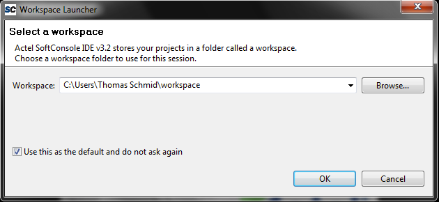
You can close all the open windows, and start SoftConsole through the Start Menu. After starting, SoftConsole will ask you for the workspace. Accept the default, mark the "Use this as the default and do not ask again" checkmark, and hit OK.
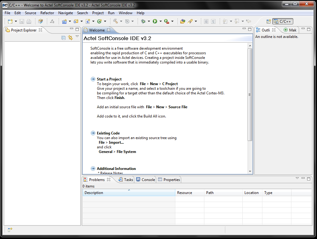
Next you will see the "C/C++ Prespective". This is the layout for Assembly or C development.
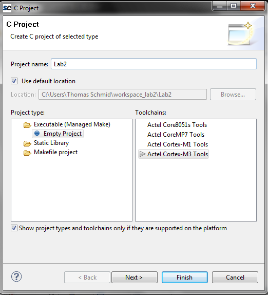
We first have to create an empty project. Click on File > New > C Project. Name the project Lab2 and make sure the Actel Cortex-M3 Tools Is selected in the Toolchains choice. Then hit finish.
Now we are ready to create an Assembly source file in SoftConsole. Click on File > New > Source File. Name the file main.s and make sure that it says Lab2 Source Folder. Change the Template to <None>. When done, hit Finish.
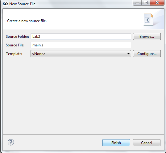
Now, copy the content from your lab2b main.s file into this one.
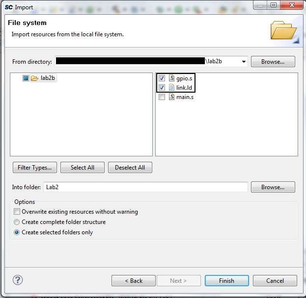
To import the gpio.s and link.ld files, right click
on the Lab2 project name on the left hand side and select
Import.... In the lower selection list, select General > File System
and click Next. Click on Browse... and select the lab2b
folder under your user name. After hitting Ok you should now see the
content of this folder in the lower selection window. Select the
gpio.s and link.ld files and click Finish. A copy of
gpio.s and link.ld now exists in the Lab2 folder.
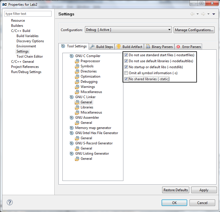
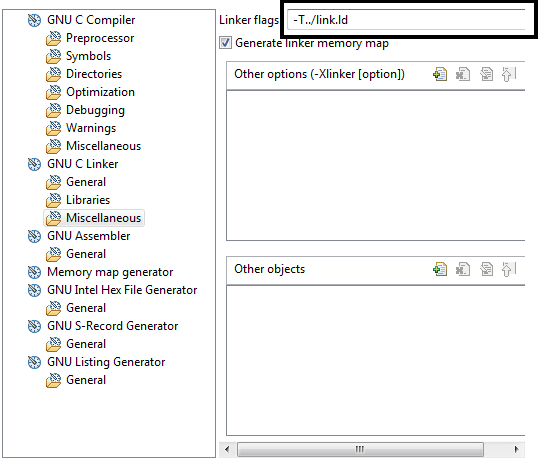
 Right click on the project folder in the Project Explorer
(left window pane) and select Properties. Then go to C/C++
Build and expand it. Select Settings and look at the Tool
Settings tab.
Right click on the project folder in the Project Explorer
(left window pane) and select Properties. Then go to C/C++
Build and expand it. Select Settings and look at the Tool
Settings tab.
Next, we have to configure our build target. Building is the process of compiling and linking all the assembly source code into the a single final binary file. This particular linker script builds an executable that runs from the SmartFusion internal SRAM. Therefore, after a reset, the program will be gone. We will see later how we can program our application into the non-volatile memory of the SmartFusion.
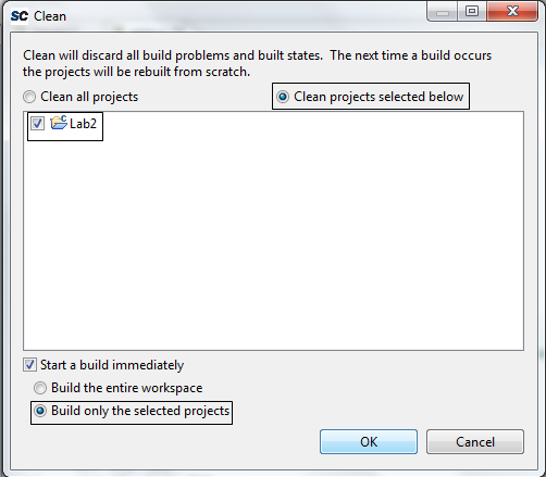
We are now ready to build our project. Click on Project > Clean... and make sure that the Lab2 project is selected. Check Clean projects selected below and Build only the selected projects. This will remove any old binaries and create the final binary for only the selected project.
If everything went well, then you should have an empty Problems tab on the bottom of your perspective. If there are problems, scroll through the Console tab to find the command that caused the problem.
From now on you can use the Hammer icon  to build. It is faster because it doesn't clean before compiling, and it only
recompiles the files that have changed. Basic build works in most cases, however,
if you run into problems perform a Clean build.
to build. It is faster because it doesn't clean before compiling, and it only
recompiles the files that have changed. Basic build works in most cases, however,
if you run into problems perform a Clean build.
Q: In the left window pane, Project Explorer, open Lab2->Debug->Lab2.lst file. Does it look familiar? How? Explain the contents of the file.
Note that by default, all the binaries build with SoftConsole contain debug information. You will also note that you got two new folders in your project named Debug and Binaries. As their names suggest, they hold debug information and the final binary respectively.
Expand the Debug folder. You will see many familiar files inside of it
that you manually created last time. The key behind everything is the
makefile inside this folder. It tells make what
targets it should compile, and which commands to run.
Now, let's program our microcontroller and start the debugging. The first time, we will have to configure our debug target. For this, right click your project Lab2 and select Debug As > Debug Configurations .... A new window will open. Right click Actel Cortex-M3 RAM Target and select New.
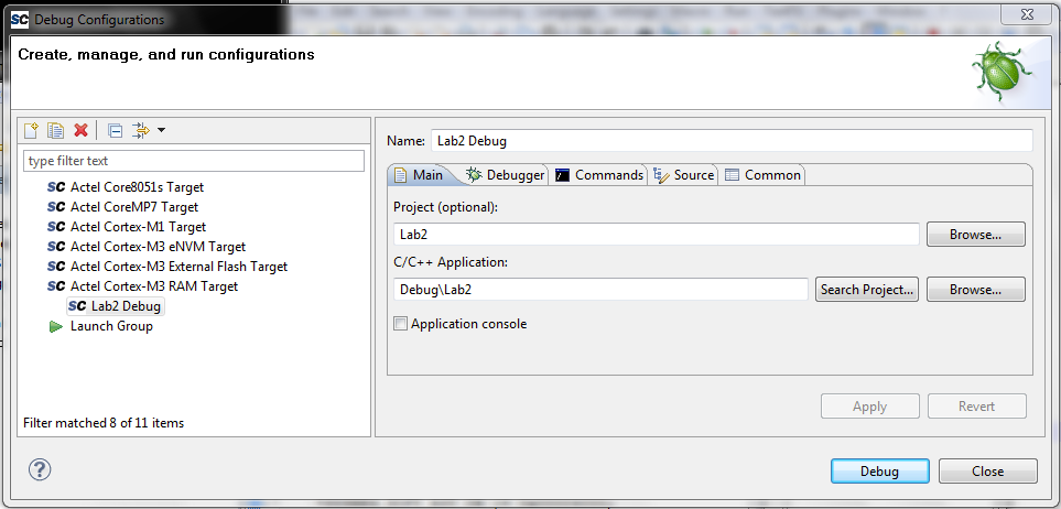
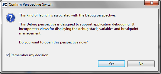
Next, click on Apply then Debug. The window will close and SoftConsole asks you if it should switch over to the Debug Perspective. Click on Remember my decision. Then click on Yes.
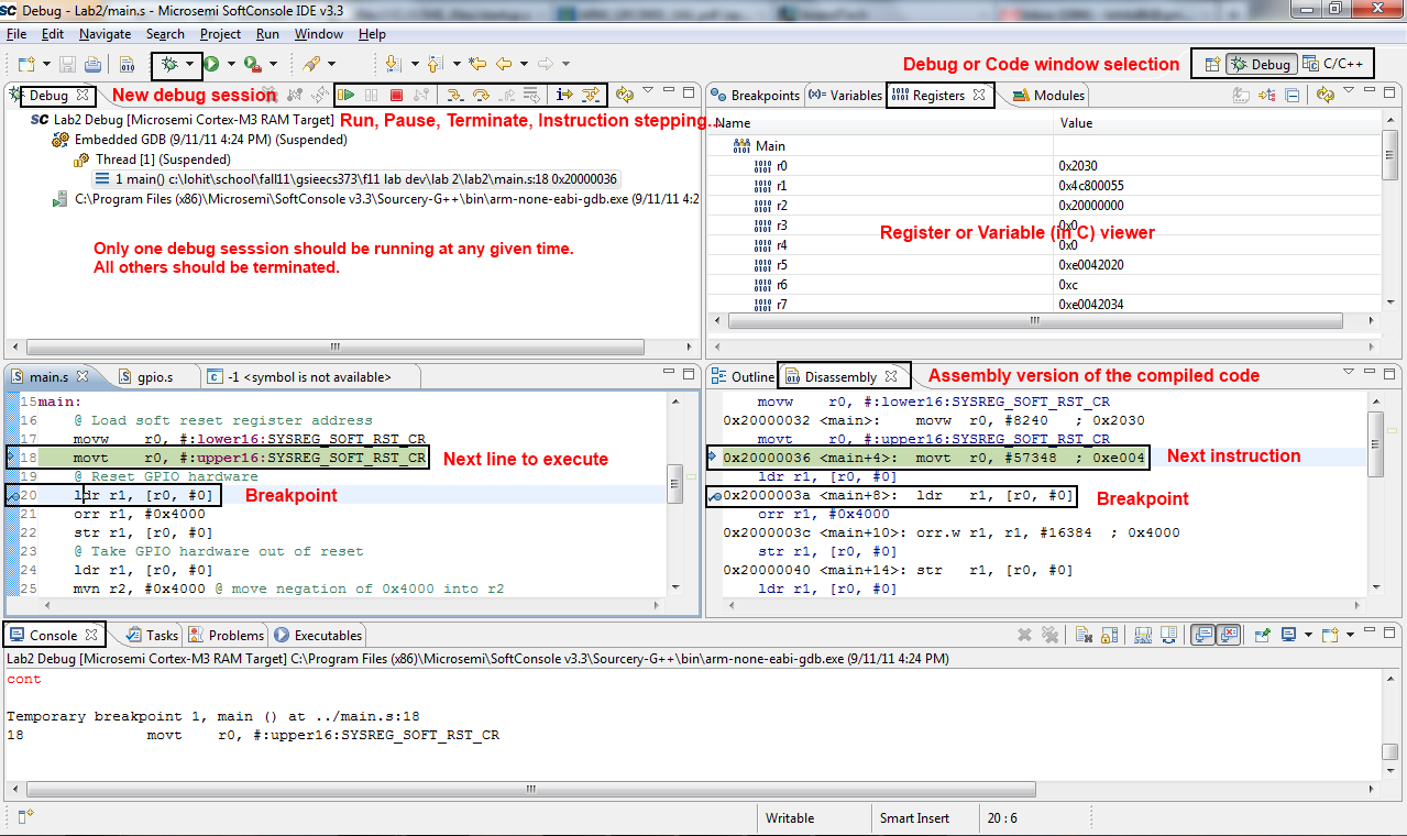
SoftConsole automatically launched GDB in the background. You can see its output in the bottom Console tab. Additionally, SoftConsole's Debug Perspective also shows you your source code, an outline of your binary, variables, breakpoints, registers, and a call trace. At the top, it gives you shortcuts to typical GDB commands you used earlier like cont (called resume, the button with the green arrow), step (called step into), next (called step over), and many more.
Try to add a breakpoint by double clicking on the space just left of the line number in your main.c file. Notice how the line gets marked with a blue-green dot, and how the breakpoint appears in the Breakpoint tab. Click the Resume button (or hit F8). Notice how your code stopped on your breakpoint. Additionally, the Variables tab updated to the current context, showing you the content of all the visible variables.
If you ever feel the need that C stepping doesn't work, and that you need to look at the disassembled code, click the Instruction Stepping Mode button on the top (the letter "i" with a right pointing arrow). A new tab will appear showing you the disassembled code at your location. Additionally, the step button now becomes a stepi instruction. You can also add breakpoints to the disassembly tab, similar as you were able to do in the C file.
Explore the capabilities of the debugger. I highly encourage you to learn the keyboard shortcuts. They will make your life much easier later on during the projects. Additionally, it speeds up your debugging a lot.
Write and Debug the following assembly code using Softconsole
gpio.s.
Use main.s as an example for modifying gpio.s.
Comments were provided in the function stubs suggesting content. Reread section 5 before
writing code.For the truly ambitious, create a "Knight Rider" effect with all the LEDs in pure Assembly. The LEDs should fade, not just toggle, between each other.
These materials can be submitted as a group. Be sure to include everyone names and unique names with the submission.
Submit the answers to the InLab questions required in the Answer Sheet. Provide your source code (gpio.s and main.s) for the 8 LED round-robin. Demonstrate to any instructor. Submit the instructors dated signature for these parts. Demonstrate Knight Ryder Bonus if you choose to do this. You can use the following Answer Sheet.