
Copyright © 2010 -
Thomas Schmid,
Matt Smith,
Ye-Sheng Kuo,
and Prabal Dutta.
See posted lab schedule for due dates, in-lab, and post-lab due dates.
The purpose of this lab is to...
Following are some paper references on Wireless Communication
There are also many good books on fundamentals of wireless communication. A very good one from David Tse and Pramod Viswanath is even available as PDFs online Fundamentals of Wireless Communication
This lab is different from the other labs. You have so far explored the fundamentals of embedded systems and understand memory, buses, peripherals, and analog to digital conversion (and back). In this lab you will have to explore and think yourself as we give you only few instructions. See this as a good preparation for the project ahead of you.
For that purpose, there is no in-lab or post-lab component. Just an assignment. The rest of this text will state the assignment and give you some more general hints and tools you can use to solve it.
Write a low-power wireless MAC protocol as described during lecture 12. We don't ask you to write one specific MAC protocol. You have to come up with your own, or implement ideas from other Low-Power MAC protocols. Your assignment will be graded by how much power you can save from the baseline, plus the ability to communicate with a second radio that runs the same MAC protocol. We will measure the power drawn of both boards and average over them. Therefore, don't just let one of the radios on all the time!
Your nodes should communicate at least once every second. In addition, you need to add visual feedback indicating when a message gets sent, or received.
You can use the following code as the baseline. It implements a simple sender/receiver application and the radios are on all the time. The SPI driver is implemented for you. However, feel free to change the design and hardware components as you wish. You can use new timer units, SPI controllers, etc, as long as the radio still works at the end.
You can use the following code to start with. It is essentially the code from Lab 6 plus the SPI driver. If your SPI driver worked well for Lab 6, then you can also use that one instead of this project.
FPGA Code: cc2520Fpga.zip
SoftConsole Workspace: cc2520Workspace.zip
You can use the following functions from cc2520driver.h to
control the radio. Feel also free to tweak parameters in cc2520.h
or the driver code in cc2520.c if you think it is necessary.
/*
 * cc2520driver.h
 *
 *  Created on: Sep 18, 2010
 *      Author: Thomas Schmid
 */

#ifndef CC2520DRIVER_H_
#define CC2520DRIVER_H_

#include "config.h"

/**
 * Initialize the radio. This function has to be called only once
 * after powerup of the whole system. It initializes all the I/O
 * lines and puts the radio into LPM1 (everything initialized, but
 * oscillators are still turned off).
 */
void Radio_init();

/**
 * Turn on the radio receiver. The CC2520 now draws about 20 mA.
 *
 * return SUCCESS if the command succeeded.
 */
error_t RadioState_turnOn();

/**
 * Put the radio into Active mode, i.e., turn off the receiver
 * while keeping the oscillators running. This draws about 1 mA.
 * The advantage is that we can quickly switch back into receive
 * mode within about 192 us.
 *
 * return SUCCESS if the command succeeded.
 */
error_t RadioState_standby();

/**
 * Put the radio back into Low Power mode 1. In this mode, the radio
 * draws about 200 uA while retaining state. The oscillators are turned
 * off, but the voltage regulator is kept on. It takes at least 0.2 ms to
 * get back into receive mode.
 *
 * return SUCCESS if the command succeeded.
 */
error_t RadioState_turnOff();

/**
 * Shutdown the radio. This turns off the voltage regulator of the radio
 * and is the lowest power possible at 0.1 uA. It takes at least 0.3 ms
 * to get back into a receive mode (not including SPI initialization).
 *
 * Currently not implemented
 *
 * return SUCCESS if the command succeeded.
 */
error_t RadioState_shutdown();

/**
 * Change the radio channel. Valid channels are 11 to 26, corresponding
 * to the 16 IEEE 802.15.4-2006 compliant channels.
 *
 * param c The radio channel to which we should switch
 * return SUCCESS if the command succeeded.
 */
error_t Radio_setRadioChannel(uint8_t c);

/**
 * Send a radio message.
 *
 * param seqn The sequence number of the message. The application developer
 *            has to assure that it is incrementing.
 * param panid The IEEE802.15.4 Personal Area Network ID. Can be used to
 *             filter messages belonging to a different network.
 * param saddr The source address of the message.
 * param daddr The destination address of the message.
 * param payload The data payload of the message.
 * param length Size in bytes of the payload.
 *
 * return SUCCESS if the command succeeded.
 */
error_t Radio_send(uint8_t seqn, uint16_t panid, uint16_t saddr, uint16_t daddr, uint8_t* payload, uint8_t length);

/**
 * This function has to be defined in your own code. It gets called when the
 * radio is done sending the message, and a new message can be sent. It is
 * kind of a callback function.
 *
 * param error SUCCESS if the message was successfully sent.
 */
void Radio_sendDone(error_t error);

/**
 * This function has to be defined in your own code. It indicates the reception
 * of a message by the radio.
 *
 * param seqn The sequence number of the message. The application developer
 *            has to assure that it is incrementing.
 * param panid The IEEE802.15.4 Personal Area Network ID. Can be used to
 *             filter messages belonging to a different network.
 * param saddr The source address of the message.
 * param daddr The destination address of the message.
 * param payload The data payload of the message.
 * param length Size in bytes of the payload.
 * param rssi The received signal strength measured during radio reception.
 */
void Radio_receive(uint8_t seqn, uint16_t panid, uint16_t saddr, uint16_t daddr, uint8_t* payload, uint8_t length, int8_t rssi);

/**
 * This function requests a clear channel assessment from the radio. The
 * return value indicates if the radio channel (or radio itself) is currently
 * busy.
 *
 * return SUCCESS if channel is free, EBUSY otherwise
 */
error_t Radio_requestCCA();

#endif /* CC2520DRIVER_H_ */
You might have wondered how your application can differentiate different types of messages. For example, how do you know that a message is an acknowledgment, and not another radio message from a different node? In general, radio's don't care about such details. They just send out whatever bytes you give them. Thus, it is the application's job to specify a message structure.
Look at the provided application in main.c. You will fine a
typedef struct at the top of the file. This newly defined type
constitutes the messages that get send over the radio for this simple counter
application. Similar to memory mapped I/O, where you can use structs to make
memory access easier and more comprehensible, here, we use structs to define
the byte sequence of a message. This particular blinkmsg_t
struct, for example, defines the first byte to be named group,
the second amtype and the third and fourth will be a
counter.
An application could now use the amtype field to differentiate
between the meaning of the counter value, or between the meaning of the
message. For example, an amtype equal to 0 could mean a regular
message, while an amtype of 1 could be an acknowledgment.
CRC stands for Cyclic Redundancy Check. It is an integrity check that
indicates to a receiving radio if the message got corrupted or not. The CRC is
automatically calculated by the radio. All the radio driver has to do is
download it (it is attached to the end of every message), and check if it is
OK or not. Thus, your application does not have to worry about message
integrity. The radio and radio driver are taking care of it. However, if your
are interested in receiving corrupted messages, then you will have to modify
the radio driver. The CRC check is done on line 1029 in cc2520.c.
We only signal a received message if the CRC turns out good. You would want to
change this to always signal a received message. However, I strongly suggest
to also change the receive interface and add the CRC field in it. Else, your
application will have difficulty to differentiate between corrupted and
non-corrupted messages.
While the radio supports automatic hardware acknowledgments, it is not
currently implemented. If you need fast turn-around times for ACKs, then you
will have to enable them. This is done by changing the radio configuration
using the writeRegister function. Find out from the TI CC2520 Manual which
register you will have to change in order to enable hardware acknowledgments.
Once enabled, the radio will send an automatic ACK message after each
successfully received message. However, you will also have to enable Frame
Filtering as you only want a radio to acknowledge messages that are destined
to its address. The CC2520 radio can automatically filter messages that are not
addressed to it, or that are not sent to the broadcast address
(0xFFFF). For this to work, you will have to change some radio
registers and let the radio know its address. Again, read through the TI
CC2520 Manual to find out how to do this.
By now you probably noticed that when you unplug your evaluation board from the USB cables, and plug it back in, your application is gone. This is because we used the volatile SRAM as build target. The eval board also has non-volatile memory. In fact, we have a total of 256 kB of Flash memory, while we "only" have 64 kB of SRAM. This means that you can write much larger and complex code if you program it into Flash. Additionally, your application will also run after you unplug it from the USB cables. This will be useful in case you want to be mobile for you project.
The disadvantage of using Flash are higher execution cost (reading/writing to flash costs more energy), limited amount of write cycles (~100k), and slower programming. Thus, you really want to first test your code using the SRAM target, where you can have a quick development cycle. Once you are sure it works, program it into the Flash for further testing.
The easy way of using the Flash is to use the predefined Debug eNVM build target provided in the lab 8 design files. This will create a binary targeted for the eNVM (i.e. Flash). The modifications I performed were the following:
Use the Debug eNVM build target to create a new binary. Once it succeeds, create a new debug configuration as follows:
After a while, Softconsole will complain that it couldn't insert a hard breakpoint. We are still trying to find out why we can't debug code in the eNVM. It should be possible, and if you find out how to do it, let us know!
In any case, your application should run now. Unplug the board from the USB cables and plug it back it. This will reset the board, and start your application.
Static variables, like predefined strings, are not located in memory anymore.
Thus, writing into them will most likely throw an exception. Therefore, you
will have to manually allocate memory for them using malloc in
order to properly use them.
As debugging currently doesn't work, you will have to rely more on
printf to find out what's going on in your application, and why
things are not working anymore. You might consider to rewrite the
HardFaultHandler to output a character on the UART. This will
help you to show that you crashed your application.
To evaluate the effectiveness of your application in conserving energy, you will have to measure the boards power draw. You can use the same setup as used in Lab 1. If you don't remember how it was done, then you can following this direct link: DMM
We measured the power of the code provided for lab 8 in order to give you a sense of how much power your board should draw.
If we don't turn off anything, use the OLED to show the result, and keep the Radio constantly on: 185 mA @ 5 V
If we put the radio into permanent standby, but busy-loop with the CPU: 166.8 mA @ 5 V
If we put the radio into permanent shutdown, but busy-loop with the CPU: 164.2 mA @ 5 V
If we keep the radio permanently ON, but use the WFI instruction between RX or TX (i.e., we wait for a received message, or a timer expires to tell us that we have to transmit): 151 mA @ 5 V
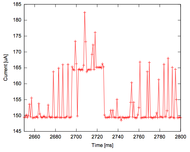
Following is a current trace of the radio receiving a message. Before the message arrives, the CPU is waiting and thus we draw just short of 150 mA. Once the radio starts receiving the message, the CPU starts downloading the message from it and thus the current jumps to 165 mA:
From the above measurements, you can see that duty-cycling the radio can conserve another ~20 mA. Thus, with a simple low-power listening scheme as described during class, we expect the power draw to be somewhere around 130 to 140 mA. You should be able to achieve this by using hardware timers to schedule your wakeup and listening periods. A good start would be to read reference 10 of the Additional Material section ("Versatile Low Power Media Access for Wireless Sensor Networks"). Note that you have to be on the University network in order to download the PDF provided on the link. This paper describes a simple low-power listening MAC protocol called B-MAC.
To save even more energy, you can start to shutdown more and more components. Following is a list of things coming to my mind.
Your application should successfully transmit and receive a message between two nodes at least once a second. On average, each node should draw less than the baseline implementation's 151 mA @ 5V.
Write a report explaining the details of your implementation. Mention why you chose your particular approach, and how effective it is. Base your reasoning on numbers measured from your board. For example: If we duty-cycle the radio at 10%, then the average power draw drops to XY mA. Switching from OLED display to LEDs reduces the current draw by XY mA, while reducing visibility, etc. Indicate what you would change or how you could improve your implementation if you had more time.
Submit a compressed file for your SoftConsole workbenches (name it
cc2520Workbench_uniquename1_uniquename2.{rar,zip,7z,bz}). In case
you modify your FPGA code, add a second compressed file containing the Libero
project (name it
cc2520Fpga_uniquename1_uniquename2.{rar,zip,7z,bz}) The workbench
should be fully configured with build targets and your code should compile.
Send all compressed files to eecs373@gmail.com with the subject
f10-lab8:uniquename1,uniquename2. Hand in your report
during the lab.
Before handing in your report, show your application to a lab staff and get a signature on your title page. We should see the power draw of your application on the DMM. Make sure the staff member puts down the current measurement next to his signature.
We will also have a small competition to see who can get the lowest power number out of their smart fusion boards, while still providing visual feedback and receiving and transmitting. The group with the lowest average power will get +25%, second lowest +10%, and third lowest +5% bonus of their grade for this lab. We will select the three lowest groups based on the numbers measured during your presentation to the staff. We will verify this number during class using precision instruments that record the power draw of the system at 1000 kHz.