
Copyright © 2010 -
Thomas Schmid,
Matt Smith,
Ye-Sheng Kuo,
and Prabal Dutta.
See posted lab schedule for due dates, in-lab, and post-lab due dates.
The purpose of this lab is to learn about the importance of timers and clocks in embedded systems.
Timers are some of the most fundamental peripherals found in embedded microcontrollers. They are used in many application scenarios, like driving motors, measuring frequencies, or measuring the event time of a particular interrupt.
You have encountered the clock system of the SmartFusion before. The bus
system AHBlite or APB3 both use the FAB_CLOCK configured in the MSS
Configurator's Clock Management block. The Clock Management has the
possibility to configure several different clocks. One of them is the clock
going into the MSS (free running clock FCLK) and clocking most of
the MSS Peripherals (exception is the 10/100 Ethernet which has its own
clock). The other clocks can be fed into the FPGA. While the MSS clock FCLK
has a recommended maximum of 100 MHz, the FPGA can use faster clocks,
depending on the logic.
In this lab, we will create a fast timer unit that runs at 120 MHz. For that
purpose, first create a new project in Libero and add a MSS component to it.
Then, open the MSS Configurator and click on the Clock Management block.
Configure the clocks as shown below. Note that you first have to enable the
GLC clock signal before you can change it's MUX. (Click image to
see larger version).
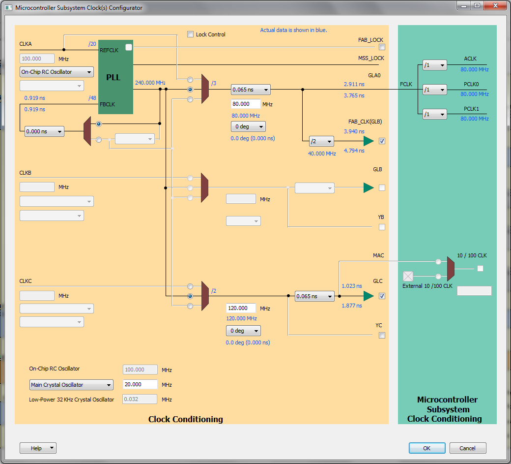
Your clocks should now be
Next, configure your MSS as shown below (click to see larger version)
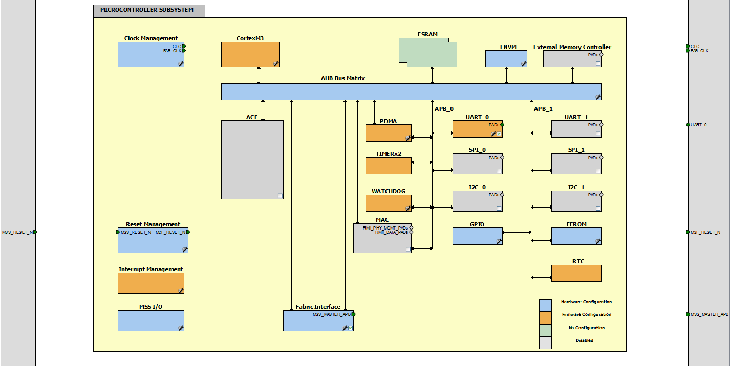
Don't forget to add the APB master interface and the MSS2FABRIC reset. We will add some more components later, once we need them.
On the Firmware tab, generate drivers for the HAL_0, GPIO, UART, Watchdog, and CMSIS. Uncheck all the other drivers. Once done, save the configuration and hit generate. If you get any errors, make sure that you relocated your vault in case you are on a shared computer!
Next, add a CoreAPB3 Bus Interface to your top level design with 1 slot and 32-bit data bus width. The timer we will create will use this slot.
The last part for the FPGA is the actual timer block. Use the following verilog timer component to start with.
// timer.v

module timer(
  PCLK,
  PENABLE,
  PSEL,
  PRESETN,
  PWRITE,
  PREADY,
  PSLVERR,
  PADDR,
  PWDATA,
  PRDATA,
  TCLK,
  test_out);

// APB Bus Interface
input PCLK,PENABLE, PSEL, PRESETN, PWRITE;
input  [31:0] PWDATA;
input  [3:0] PADDR;
output [31:0] PRDATA;
output PREADY, PSLVERR;

// Timer Interface
input TCLK;

// Test Interface
output [3:0] test_out;

// Clock Domain synchronization
reg PREADY;
reg [1:0] fsm; //state machine register for pclk domain
reg fsm_tclk;  // state machine register for tclk domain
reg [31:0]   PRDATA;

// Timer
reg [31:0] Counter;
reg [31:0] Load;
reg TimerEn;   // Timer enable
reg LoadEnReg; // Register Load enable

// Handshaking signals
reg reg_load_en0, reg_load_en1, reg_load_en2;
reg reg_load_ack0, reg_load_ack1, reg_load_ack2;

// Test Outputs
wire [3:0] test_out;
assign test_out[0] = 1'b0;
assign test_out[1] = 1'b0;
assign test_out[2] = 1'b0;
assign test_out[3] = 1'b0;

assign PSLVERR = 1'b0;

// Handshaking signal PCLK signals to TCLK
always@(posedge PCLK or negedge PRESETN)
if(~PRESETN)
  begin
    reg_load_en1 <= 1'b0;
    reg_load_en2 <= 1'b0;
  end
else
  begin
    reg_load_en1 <= reg_load_en0;
    reg_load_en2 <= reg_load_en1;
  end

// Handshaking signal TCLK signals to PCLK
always@(posedge TCLK or negedge PRESETN)
if(~PRESETN)
  begin
    reg_load_ack1 <= 1'b0;
    reg_load_ack2 <= 1'b0;
  end
else
  begin
    reg_load_ack1 <= reg_load_ack0;
    reg_load_ack2 <= reg_load_ack1;
  end

// Handle APB Bus read and writes and inform TCLK clock domain
always@(posedge PCLK or negedge PRESETN)
if(~PRESETN)
  begin
      fsm <= 2'b00;
      PREADY <= 1'b1;
      reg_load_en0 <= 1'b0;
      end
else
  begin
  case (fsm)
     2'b00 :  begin
                  if (~PSEL)
                        begin
                          // not for us
                          fsm <= 2'b00;
                        end
                  else
                        begin
                          fsm <= 2'b01; // advance to next state
                          PREADY <= 1'b0; // signal we are not ready
                          reg_load_en0 <= 1'b1; // inform other clock domain
                        end
               end

     2'b01 :  begin
                if(reg_load_ack2 == 1'b1)
                  begin
                    fsm <= 2'b10;
                    reg_load_en0 <= 1'b0;
                  end
              end

     2'b10 :  begin
                if(reg_load_ack2 == 1'b0)
                  begin
                    fsm <= 2'b11;
                    PREADY <= 1'b1; // we are ready
                  end
              end

     2'b11 :  begin
                fsm <= 2'b00;
              end

    default : fsm <= 2'b00;
  endcase
end

always@(posedge TCLK or negedge PRESETN)
if(~PRESETN)
  begin
    fsm_tclk <= 1'b0;
    reg_load_ack0 <= 1'b0;
    LoadEnReg <= 1'b0;
    TimerEn <= 1'b0;
    Load <= 32'h00000000;
  end
else
  begin
    case (fsm_tclk)
      1'b0: begin
              if(reg_load_en2 == 1'b1) // signal from other clock domain
                begin
                  if(PWRITE)
                    begin // it's a write
                        case(PADDR[3:2])
                          2'b00: begin // Timer Load register
                                    Load <= PWDATA;
                                    LoadEnReg <= 1'b1;
                                 end
                          2'b01: begin // Timer Value, no write
                                    LoadEnReg <= 1'b0;
                                 end
                          2'b10: begin // Timer Control
                                    LoadEnReg <= 1'b0;
                                    TimerEn <= PWDATA[0];
                                 end
                          2'b11: begin // spare
                                    LoadEnReg <= 1'b0;
                                 end
                        endcase
                    end
                  else
                    begin // it's a read
                        case(PADDR[3:2])
                          2'b00: begin // Timer Load register
                                    PRDATA <= Load;
                                 end
                          2'b01: begin // Timer Value, no write
                                    PRDATA <= Counter;
                                 end
                          2'b10: begin // Timer Control
                                    PRDATA[31:1] <= 31'h00000000;
                                    PRDATA[0] <= TimerEn;
                                 end
                          2'b11: begin // spare
                                 end
                        endcase
                    end
                  fsm_tclk <= 1'b1; // advance state
                  reg_load_ack0 <= 1'b1; // signal other domain
                end
            end
      1'b1: begin
              if (reg_load_en2 == 1'b0)
                begin
                  fsm_tclk <= 1'b0;
                  reg_load_ack0 <= 1'b0;
                  LoadEnReg <= 1'b0;
                end
            end
      default: fsm_tclk <= 1'b0;
    endcase
  end


always@(posedge TCLK or negedge PRESETN)
if(~PRESETN)
  begin
    Counter <= 32'h00000000;
  end
else
  begin
    if(LoadEnReg == 1'b1)
      begin
        Counter <= 32'h00000000;
      end
    else if(TimerEn == 1'b1)
      begin
        if(Counter == Load)
          begin
            Counter <= 32'h00000000;
          end
        else
          begin
            Counter <= Counter + 1;
          end
      end
  end

endmodule
Go through the code and try to understand it. As you can see, it does have an APB bus interface. However, it uses two clocks! Because we do not know what the phase between the clocks is, we have to be extremely careful in passing data from one clock domain (the bus) to the other (the timer).
Finish your FPGA design by wiring up the timer as shown below. Note that we didn't connect the test_out signal to anything. If you wish, connect them to the 4 user I/O lines of the eval board. They can become handy to debug your code later on:
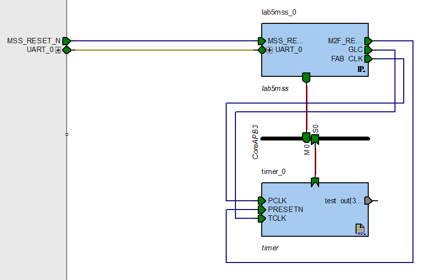
Note that we connected the FAB_CLK to the bus interface's
PCLK and the GLC clock to the timer clock
TCLK.
Passing between different clock domains is always dangerous and prone to glitches, i.e., one domain is updating a value, while the other domain starts already reading it. This will eventually lead to corrupted data and information. We have seen such a problem already in the last lab where we had to synchronize the switch I/O line to the clock system using 3 signals.
This time, we have to synchronize the APB bus domain clocked by PCLK to the timer domain clocked by TCLK. We achieve this by a hand-shaking mechanism.
Find the two hand-shaking blocks at the beginning of timer.v. Notice
how one of the blocks is sensitive to PCLK, while the other one is
sensitive to TCLK. Similar to the switch synchronization, we also use 3
signals each way, i.e., reg_load_enX to signal from the bus to
the timer domain, and reg_load_ackX from the timer to the bus
domain.
The signals are used to synchronize the two state machines in timer.v.
Draw the state diagrams for both state machines. Whenever a signal influences the state of the other state machine, draw an arrow from that variable to the state in the other state machine.
Our timer is still very simple and has only 3 registers defined:
| Offset | Type | Reset | Name | Description |
|---|---|---|---|---|
| 0x0 | W | 0 | Load | Timer Load |
| 0x4 | R | 0 | Counter | Timer Value |
| 0x8 | R/W | 0 | Timer Control Bit 0: Enable bit |
The configuration bit 0 enables or disables the incrementing counter. When
enabled, the counter will increment up to the value stored in the
Load register. Once reached, it resets to 0 and starts counting
again. The Value registers contains the current value of the
counter.
Now it's time to generate your smart design, synthesize it, place and route it, and then program your FPGA with it.
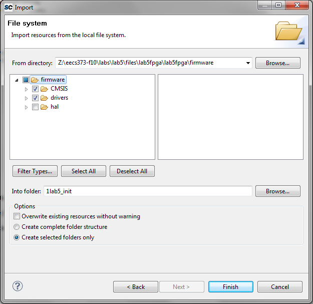
We will now write a simple timer library that you can use in your application. Create a new SoftConsole Project and import the CMSIS and drivers folders from the firmware directory.
Add files for main.c, mytimer.c, and mytimer.h.
Following is the content for main.c:
#include <stdio.h>
#include "drivers/mss_uart/mss_uart.h"
#include "drivers/mss_watchdog/mss_watchdog.h"
#include "mytimer.h"

int main()
{
    /* Watchdog Disabling function */
    MSS_WD_disable();

    /* Setup MYTIMER */
    MYTIMER_init();
    MYTIMER_load((1<<31));
    MYTIMER_enable();

    while(1)
    {
        uint32_t i;
        printf("Time: %lu\r\n", MYTIMER_value());
        for(i=1e6; i>0; i--);
    }
    return 0;
}
Following is the content for mytimer.c:
#include "mytimer.h"

void MYTIMER_init()
{
    // we don't have to do anything.
}

void MYTIMER_enable()
{
    MYTIMER->control |= MYTIMER_ENABLE_MASK;
}

void MYTIMER_disable()
{
    MYTIMER->control &= ~MYTIMER_ENABLE_MASK;
}

void MYTIMER_load(uint32_t load)
{
    MYTIMER->load = load;
}

uint32_t MYTIMER_value()
{
    return MYTIMER->value;
}
Following is the content for mytimer.h:
#ifndef MYTIMER_H_
#define MYTIMER_H_

#include "CMSIS/a2fxxxm3.h"

#define MYTIMER_BASE (FPGA_FABRIC_BASE + 0x0)

typedef struct
{
    __IO uint32_t load;
    __I  uint32_t value;
    __IO uint32_t control;
} mytimer_t;

#define MYTIMER_ENABLE_MASK 0x00000001UL

#define MYTIMER ((mytimer_t *) MYTIMER_BASE)

/**
 * Initialize the MYTIMER
 */
void MYTIMER_init();

/**
 * Start MYTIMER
 */
void MYTIMER_enable();

/**
 * Stop MYTIMER
 */
void MYTIMER_disable();

/**
 * Set the limit to which the timer counts.
 */
void MYTIMER_load(uint32_t load);

/**
 * Read the counter value of the timer.
 */
uint32_t MYTIMER_value();


#endif /* MYTIMER_H_ */
Note how the three files play together, and how we defined the timer library. Using a simple structure, we index all the registers available on the timer peripheral. This is a very typical way of writing peripheral drivers. For example, look at the files in drivers/mss_uart. You will see that they follow a similar structure.
What is the purpose of the __I and __IO in the
typedef of mytimer_t? Are there any other modifiers?
Explain in two sentences.
Don't forget to define the ACTEL_STDIO_THRU_UART to allow
printf to work. See Lab 4 if you are unsure on how to do this.
You will also have to add the linker script to the GNU Linker setting of the
project, before you will be able to compile your code.
Compile your code and run the application. Connect the serial terminal application to the serial port of the eval board. You should now see numbers being printed on your terminal.
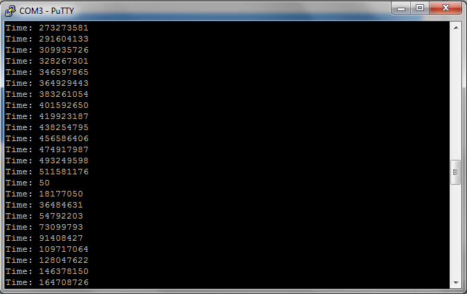
You can see that the numbers overflow after a certain amount of time. Measure that time using a stop watch and calculate the clock frequency. Write down your result. Does it agree with the frequency specified in the MSS Configurator Clock Manager block? Explain in two sentences.
So far, your timer unit provides you time through a software interface. We will now add some more functionality. One of the basic functions of a timer is a timed interrupt. You program the timer unit with a specific time, and an interrupt will fire upon reaching that time.
In the last lab, you learned how to create interrupts on the FPGA, and how to process them in the interrupt service routine. Let's add two interrupt sources to our timer, both sharing the same interrupt line FABINT. An interrupt register will indicate in software which interrupt actually fired. This is very similar to the last lab where we had two interrupt sources, the two switches, sharing the FABINT interrupt line.
The two interrupt sources should fire when the timer reaches two specific values:
Load valueCompare valueCompare value.
Together with the interrupts, we will also need some more control bits
The one thing we will have to be careful about is the different clock domains. As in the last lab, the timer should be considered asynchronous to the fabric clock. Thus, you will have to use a similar technique to provide a synchronous interrupt to the fabint.
In summary, we will make the following modifications to the code:
The perform all the steps above, use the following verilog code: timer_with_interrupts.v. Replace
your previous timer.v file with this implementation and update your smart
designer correspondingly. Don't forget to add the FAB_INT to your
MSS component!
Having more functionality in your peripheral necessitates to update your timer driver. Add the following additional functions form this header file to your library. Make sure that the different enable and disable functions really toggle the right bits in the configuration register.:
/**
 * Enable all interrupts
 */
void MYTIMER_enable_interrupts();

/**
 * Disable all interrupts
 */
void MYTIMER_disable_interrupts();

/**
 * Enable compare interrupt
 */
void MYTIMER_enable_compare();

/**
 * Disable compare interrupt
 */
void MYTIMER_disable_compare();

/**
 * Set Compare value
 */
void MYTIMER_compare(uint32_t compare);

/**
 * Enable overflow interrupt
 */
void MYTIMER_enable_overflow();

/**
 * Disable overflow interrupt
 */
void MYTIMER_disable_overflow();

 /**
  * Interrupt status
  */
uint32_t MYTIMER_interrupt_status();
Implement the missing MYTIMER functions in your
timer.c file.
Once implemented, replace your main function with the following
code. Notice that we added the Fabric interrupt handler too:
__attribute__ ((interrupt)) void Fabric_IRQHandler( void )
{
    uint32_t time = MYTIMER_value();
    uint32_t status = MYTIMER_interrupt_status();

    printf("Interrupt occurred at %lu FABINT \n\r", time);

    if(status & 0x01)
    {
        printf("Overflow latency %ld\n\r", 0-time);
    }
    if(status & 0x02)
    {
        printf("Compare latency %ld\n\r", (1<<29) - time);
    }
    NVIC_ClearPendingIRQ( Fabric_IRQn );
}

int main()
{
    /* Watchdog Disabling function */
    MSS_WD_disable();

    /* Setup MYTIMER */
    MYTIMER_init();
    MYTIMER_load((1<<30));
    MYTIMER_compare((1<<29)); // 50%

    MYTIMER_enable_overflow();
    MYTIMER_enable_compare();
    MYTIMER_enable_interrupts();

    NVIC_EnableIRQ(Fabric_IRQn);

    MYTIMER_enable();

    while(1){}
    return 0;
}
Program your eval board with the application and connect the serial terminal.
Observe the latency and convert it to seconds, either in your output by
modifying the printf functions, or on paper.
How does the latency compare to the latency measured with the oscilloscope in Lab 4? Explain in two sentences.
We have almost all the pieces together for a Pulse Width Modulated (PWM) signal generator. PWM signals are very common in embedded systems to deliver a variable amount of energy to an end system, such as LEDs, robotic servos, heating plates, etc. There are two parameters to a PWM system: frequency and duty-cycle. The frequency indicates how often we have a positive edge, while the duty-cycle describes the amount of high time vs. low time of the signal, and is usually expressed in percent. For example, a system that has a pulse every second, then stays on for 100 milliseconds, before going low for 900 milliseconds would have a duty cycle of 10%.
With the timer unit we have, it is really easy to generate a PWM system. We
just have to set a signal to high when we get to the
Compare value, and set it back to low when we reach
Load. In that respect, the Load value will determine
the period, or frequency, of our signal, while the Compare value
determines the duty cycle.
Modify the timer unit and add the PWM output. Add a control register bit that can enable and disable that output. Connect the PWM output to one of the LEDs on your eval board.
Add PWM capabilities to your timer library, and write an application that generates a PWM signal at 100Hz and changes the duty cycle from 0 to 100% over 1 second. Observe the signal on an oscilloscope and the LED. Describe your observation in a few sentences and include a screenshot of the oscilloscope.
The compare capabilities of a timer allow timed events to happen. The Capture capabilities allow the inverse, i.e., they measure the time of external events. As you saw in the last lab, the handling of interrupt service routines can have significant latency and jitter. Thus, we can not just read the time in software once we entered an interrupt service routine. The capture unit instead grabs the current time inside the timer unit and stores it in a register. It then signals to the core using the timer interrupt that a capture happened. The software can then, at its own convenience, read the capture register.
Let's add capture capabilities to our timer unit:
Use the following file as a reference to implement the above capabilities: timer_with_captures.v. Make sure you connect one of the switches to the capture input. Synthesize, place and route, and program the eval board with your new code.
We now have to add the new capabilities to our timer library. Implement the
following new functions in your mytimer.c file.
/**
 * Enable Capture
 */
void MYTIMER_enable_capture();

/**
 * Disable Capture
 */
void MYTIMER_disable_capture();

/**
 * Read the synchronous capture value
 */
uint32_t MYTIMER_sync_capture();

/**
 * Read the asynchronous capture value
 */
uint32_t MYTIMER_async_capture();

/**
 * Returns 1 if the capture has been overwritten.
 */
uint8_t MYTIMER_capture_overwrite();
Write a little application that upon pressing the switch outputs the synchronous and asynchronous capture times, including the difference between them.
What do you observe between the synchronous and asynchronous capture values? Explain in a couple of sentences.
Change the GLC clock to 2.5 MHz, instead of 120 MHz and repeat the last experiment. Again, explain your findings.
Write a small reaction game. At a specific time, using the PWM output, toggle the LED on. The user has to hit the push button when he sees the light turning on. Then, output the time difference between LED toggle and button push on the serial terminal. How good is your reaction time in seconds?
Did you notice the  symbol during the place
and route of your timer unit in
symbol during the place
and route of your timer unit in
During the timer lecture, we talked about virtualizing a hardware timer in software, such that it can be shared by several software routines. Implement the timer virtualization interface provided during the lecture, and write an application using it. The application should toggle the 8 LEDs. But every LED should toggle at a different rate, and it should be toggled from its own timer handler.
Using the notation provided during the timer lecture, your main.c
function should looks something like this. Note that left out the toggling of
LED code and the initialization of your hardware timer from this pseudo code
for brevity reasons:
#include "myvirtualtimer.h"

void led0() {
    // toggle LED 0
}

void led1() {
    // toggle LED 1
}

...

void led7() {
    // toggle LED 7
}

int main() {

    initTimer();

    startTimerContinuous(&led0, 200);
    startTimerContinuous(&led1, 32768);
    ....
    startTimerContinuous(&led7, 1e8);


    while(1){}

    return 0;
}
For reference, following is the proposed myvirtualtimer.h file:
typedef void (*timer_handler_t)(void);

typedef struct timer
{
    timer_handler_t handler;
    uint32_t        time;
    uint8_t         mode;
    timer_t*        next_timer;
} timer_t;


/* initialize the virtual timer */
void initTimer();

/* start a timer that fires at time t */
error_t startTimerOneShot(timer_handler_t handler, uint32_t t);

/* start a timer that fires every dt time interval*/
error_t startTimerContinuous(timer_handler_t handler, uint32_t dt);

/* stop timer with given handler */
error_t stopTimer(timer_handler_t handler);
And following is a proposed myvirtualtimer.c file including
pseudo code:
#include "myvirtualtimer.h"

timer_t* current_timer;

void initTimer() {
    setupHardwareTimer();
    initLinkedList();
    current_timer = NULL;
}

error_t startTimerOneShot(timer_handler_t handler, uint32_t t) {
    // add handler to linked list and sort it by time
    // if hardware timer not running, start hardware timer
}

error_t startTimerContinuous(timer_handler_t handler, uint32_t dt) {
    // add handler to linked list for (now+dt), set mode to continuous
    // if hardware timer not running, start hardware timer
}

error_t stopTimer(timer_handler_t handler) {
    // find element for handler and remove it from list
}

__attribute__((__interrupt__)) void Timer1_IRQHandler() {
    timer_t * timer;
    MSS_TIM1_clear_irq();
    NVIC_ClearPendingIRQ( Timer1_IRQn );
    timer = current_timer;

    if( current_timer->mode == CONTINUOUS ) {
        // add back into sorted linked list for (now+current_timer->time)
    }

    current_timer = current_timer->next_timer;

    if( current_timer != NULL ) {
        // set hardware timer to current_timer->time
        MSS_TIM1_enable_irq();
    } else {
        MSS_TIM1_disable_irq();
    }

    (*timer->handler))(); // call the timer handler

    if( timer->mode != CONTINUOUS ) {
        free(timer); // free the memory as timer is not needed anymore
    }
}
This pseudo code uses the MSS System Timer 1 as timed interrupt source. Feel
free to use your own timer implementation from this lab. Or, you can use the
System Timer 1, though you will have to figure out how to initialize it in your
initTimer function.
You may work with a partner for this assignment. Submit a zip file of your SoftConsole workbench, and a second zip file of your Libero project for your post lab assignment to eecs373@gmail.com with the subject f10-lab5:uniquename1,uniquename2. Hand in your answers from the questions asked during the lab. You can use the following Answer Sheet. Before handing your solution in, show your application to a lab staff and get a signature on your title page.